- In the tree view, right-click on Constraints under Subcase 1 and choose New.
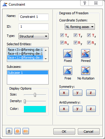
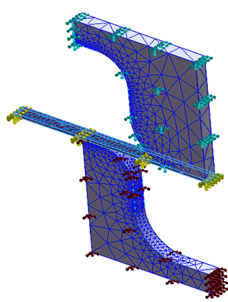
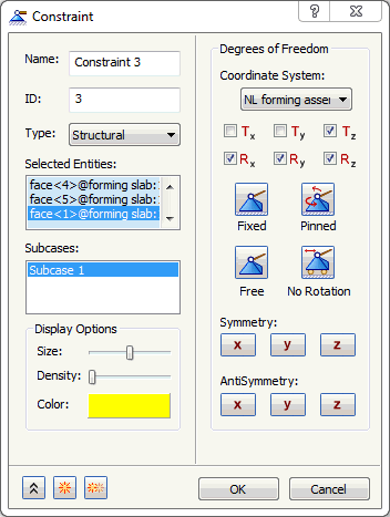
- Select all the side faces of the die except the contacting face, and also select the slab end face as shown in the image below. Click on the Fixed button.
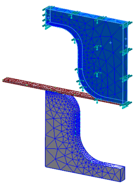
- Be sure that Subcase 1 is selected in the Subcases list.
- Click on
 New button.
- Change the color to Brown.
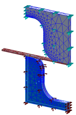
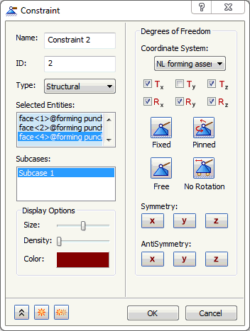
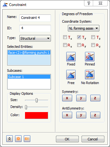
- Select all the side faces of the punch model except the contacting face. Click on the Fixed button and unselect Ty as shown in the image below.
- Click on New button.
- Change the color to Yellow.
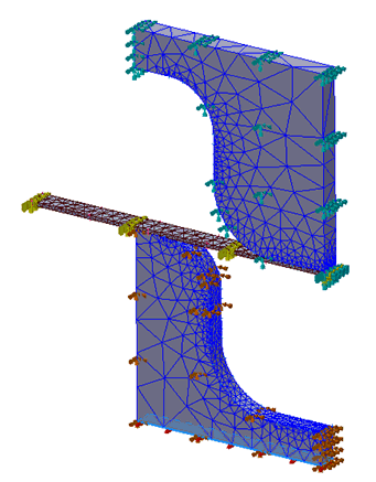
- Select all the faces of the slab model except the fixed end. Uncheck Tx and Ty as shown in the image below.
- Click on New button.
- Change the color to Red.
- Select the bottom face of the punch model. Click on the Free button and select Ty as shown in the image below.
- Click OK to create the constraint in Y direction for the enforced displacement load.