- The results are automatically loaded into Autodesk Nastran In-CAD.
- You will now look at various composite results.
-
COMP MAX PLY FAILURE INDEX
- Right-click on von Mises under Results and choose Edit.
- Select COMP MAX PLY FAIL INDEX for the Results Data under Contour Options. Make sure Deform and Contour are selected.
- Change the Data Type drop-down to Centroidal, the Contour Type drop-down to Elemental, and check the No Averaging checkbox.
- Uncheck
Max/Min under
Display Options.
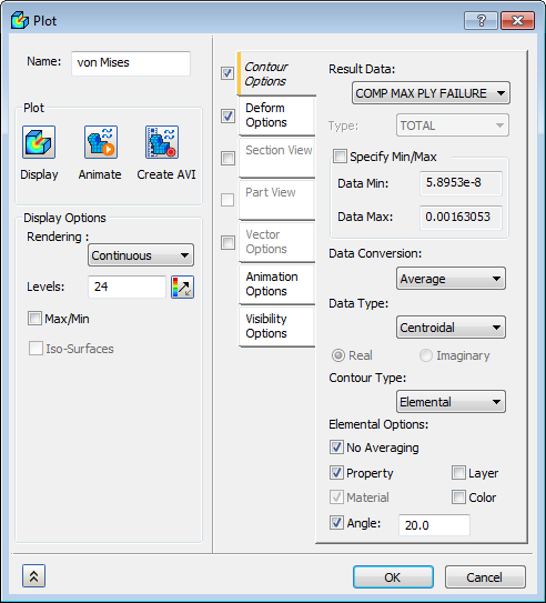
- Click Display.
- Click
OK.
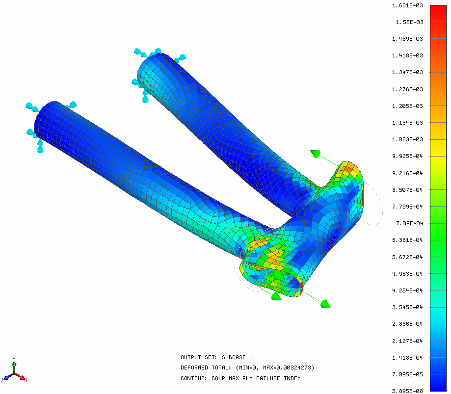
 This result output vector shows you the maximum occurring failure index (calculated using the Hill composite failure theory) on each element. When the failure index is over 1.0, first ply failure is predicted, meaning at least one ply has failed. When the failure index is less than 1.0, no failure is predicted to occur.
-
COMP MAX FAILURE INDEX PLY
- Right-click on Displacement and select Edit.
- Change the Result Data to COMP MAX FAILURE INDEX PLY.
- Change Levels from 24 to 12.
- Change Rendering to Fringe.
- Uncheck
Max/Min under
Display Options.
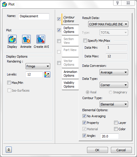
- Click Display.
- Click
OK.
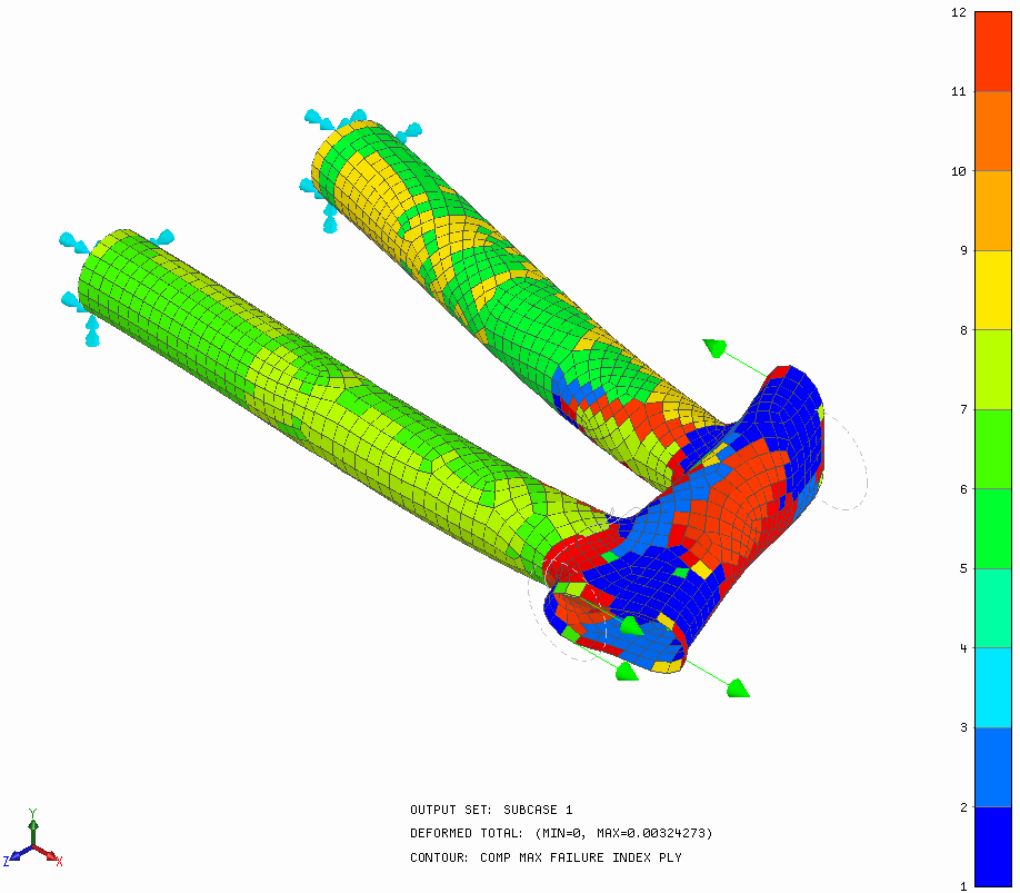 COMP MAX FAILURE INDEX PLY indicates what ply is most critical and has the highest failure index.
-
COMP PLY 1 NORMAL-1
- Right-click on Displacement and select Edit.
- Change the Result Data to COMP PLY 1 NORMAL-1 STRESS.
- Change the Levels from 12 to 24 and Rendering to Continuous.
- Click Display.
- Click
OK.
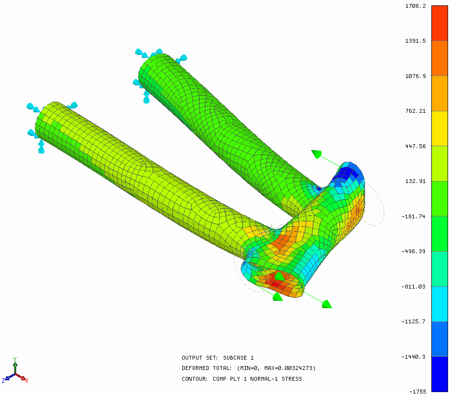 COMP PLY 1 NORMAL–1 STRESS is the stress along the fiber direction for ply 1. COMP PLY 1 NORMAL-2 STRESS is the stress in the transverse fiber direction for ply 1.
-
COMP MAX PLY FAILURE INDEX
This concludes Using Composite Materials in a Bike Frame Section.
The following summarizes the main topics covered:
- Running an analysis with a composite material.
- How to set up a laminate physical property.
- How to configure a material orientation.
- How to use shell modeling.
- How to extract the maximum failure index.
- How to extract the ply where the maximum failure index is occurring.
- How to interpret ply normal stresses.