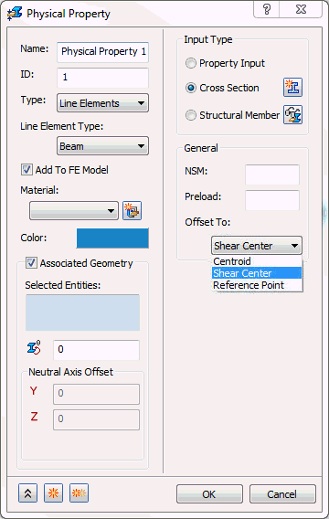
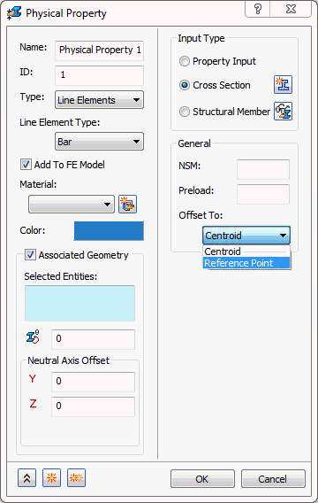
Select the Line Elements option under Type in the Physical Property form.
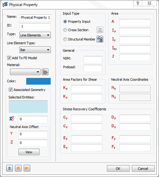
Under Line Element Type you can then select different types of line elements: Bar, Beam and Pipe.
- Bar: 1D element with six degrees of freedom per node. It has the options to use either
Property Input,
Cross Section, or
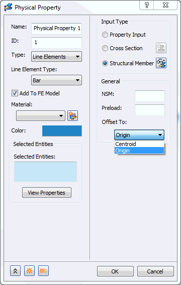
Structural Member (SolidWorks versions only) under
Input Type. You will find more details about these options at the end of this section.

- NSM: Defines non-structural mass for this element type.
- Preload: A preload value can be input on the Bar element. Used for modeling connections that have preload.
- Offset To: This allows you to offset 1D Bar elements. This drop-down list will change depending upon the type of bar element input (Structural Member,
Property Input or
Cross Section). It consists of
Centroid and
Reference Point options for
Cross Section. For
Structural Member it consists of
Centroid and
Origin.
- Centroid: This is used as the default for Bar elements.
- Reference Point: Used for cross section definition. A reference point can be assigned to a location on the cross section and then the section offset to this reference point location.
- Origin: Uses the origin of the structural member cross section as the offset point.
- Offset vectors are treated like rigid elements and are therefore subject to the same limitations.
- Offset vectors do not affect thermal loads.
- The specification of offset vectors is not recommended in solutions that compute differential stiffness because the offset vector remains parallel to its original orientation (differential stiffness is computed in buckling, prestress, and nonlinear analysis with large displacement effects ON).
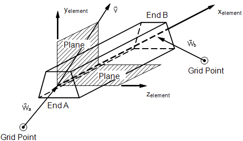
Bar Element Geometry
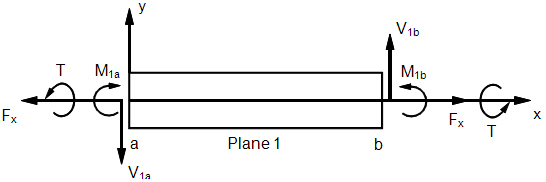
Bar Element Internal Forces and Moments (xy-Plane)
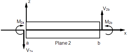
Bar Element Internal Forces and Moments (xz-Plane)
- Beam: 1D element with six degrees of freedom per node, where the shear center can be offset. It has the options to use
Property Input,
Cross Section, or
Structural Member (SolidWorks versions only) under
Input Type.

- NSM: Defines non-structural mass for this element type.
- Preload: A preload value can be input on the Beam element. Used for modeling connections that have preload.
- Offset To:
Centroid (default),
Shear Center,
Reference Point, and
Origin. These options refer to the actual mesh (numerical representation) of the model.
- Centroid: Will always mesh to the centroid of the library part used no matter how it looks on the screen.
- Shear Center: Will mesh the selected structural members to the offset shear center.
- Reference Point: Used for cross section definition. A reference point can be assigned to a location on the cross section and then the section offset to this reference point location.
- Origin: Will mesh the selected structural members to the offset origin of the library file used. Used only for Structural Members.
- Offset vectors are treated like rigid elements and are therefore subject to the same limitations.
- Offset vectors do not affect thermal loads.
- The specification of offset vectors is not recommended in solutions that compute differential stiffness because the offset vector remains parallel to its original orientation (differential stiffness is computed in buckling, prestress, and nonlinear analysis with large displacement effects ON).
- The following figure defines beam element geometry:
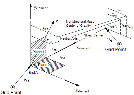
Beam Element Geometry System
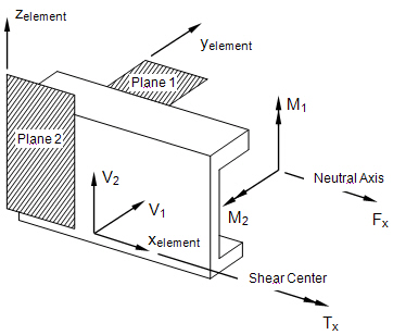
Beam Internal Element Forces and Moments
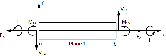
Beam Element Internal Forces and Moments (xy-Plane)
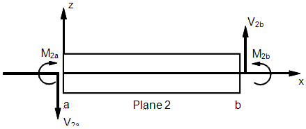
Beam Element Internal Forces and Moments (xz-Plane)
- Pipe: 1D element with six degrees of freedom per node with the option of internal pressure. It has the options to use
Property Input,
Cross Section, or
Structural Member (SolidWorks versions only) under
Input Type.
- When the
Property Input is selected, the following form comes up:
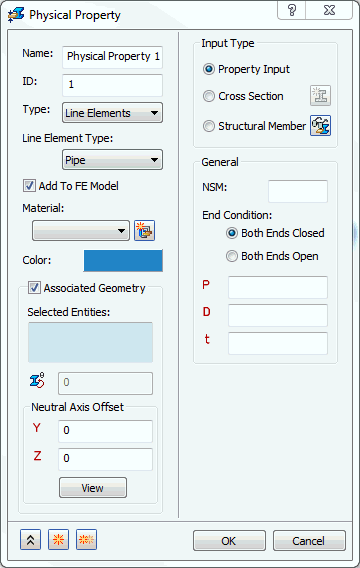
- NSM: Defines non-structural mass for this element type.
- End Condition: Tells the solver that the line element is closed at both ends when the Both Ends Closed option is selected. Both Ends Open option tells the solver that the line element is open at both ends.
- P: Defines the internal pressure of the pipe.
- D: Defines the diameter of the pipe.
- t: Defines the thickness of the pipe.
- When the
Cross Section is selected, the following form comes up:
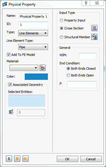
- NSM: Defines non-structural mass for this element type.
- End Condition: Tells the solver that the line element is closed at both ends when the Both Ends Closed option is selected. Both Ends Open option tells the solver that the line element is open at both ends.
- P: Allows you to input an internal pressure.
- When the
Property Input is selected, the following form comes up:
As explained at the beginning of this topic, no matter what line element type is selected, there are three options under the Input Type section: Property Input, Cross Section and Structural Member (SolidWorks versions only).
- Property Input: This option allows you to create a structural member by inputting structural member properties.
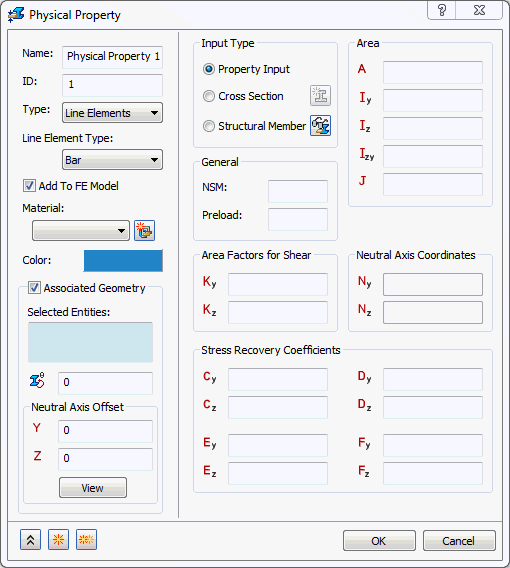
- NSM: A non-structural mass for the line elements will be used in calculations.
- Preload: Defines an axial preload value (not for use in nonlinear solutions).
- Area: Cross section area.
- Iz: Moment of inertia about Zn.
- Iy: Moment of inertia about Yn.
- Izy: Product of inertia.
- J: Torsional Constant.
- Kz: Shear factor in Z.
- Ky: Shear factor in Y.
- Nz: Centroid offset from shear center in Z (appears only for Beam type).
- Ny: Centroid offset from shear center in Y (appears only for Beam type).
- Cz: Z coordinate of stress recovery point C.
- Cy: Y coordinate of stress recovery point C.
- Dz: Z coordinate of stress recovery point D.
- Dy: Y coordinate of stress recovery point D.
- Ez: Z coordinate of stress recovery point E.
- Ey: Y coordinate of stress recovery point E.
- Fz: Z coordinate of stress recovery point F.
- Fy: Y coordinate of stress recovery point F.
- Cross Section: This option allows you to define the cross section based upon dimensions and section templates. Using the
Cross Section selection you can define a 1D element as a
PBEAML,
PBARL, or
PPIPE. More information can be found in the Autodesk Nastran User’s Manual regarding the significance of using a PBEAML, PBARL, and PPIPE.
- The
 icon brings up the
Cross Section Definition window. This is where the cross sectional dimensions for a Beam, Bar or a Pipe element are defined.
icon brings up the
Cross Section Definition window. This is where the cross sectional dimensions for a Beam, Bar or a Pipe element are defined.
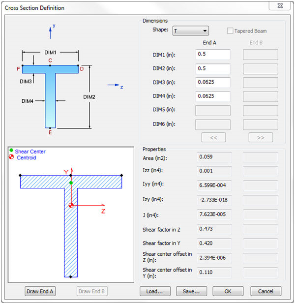
- The general shape of the cross section is selected by using the Shape drop-down list (T, I, Chan, etc.).
- The dimensions are then filled in according to the shape image. DIM1, DIM2, etc.
- Once the cross section dimensions are filled in, the Draw End A or Draw End B buttons may be used to draw the shape based on the dimensions.
- The Tapered Beam option is available, but only when the Element Type is set to Beam. This will allow you to use the End B column of dimensions.
- The
 and
and
 buttons will become active when
Offset To option is set to
Reference Point. This will activate a reference point that can be moved around the cross section as an offset location for a beam. (Typically this is used with stiffening panels.)
buttons will become active when
Offset To option is set to
Reference Point. This will activate a reference point that can be moved around the cross section as an offset location for a beam. (Typically this is used with stiffening panels.)
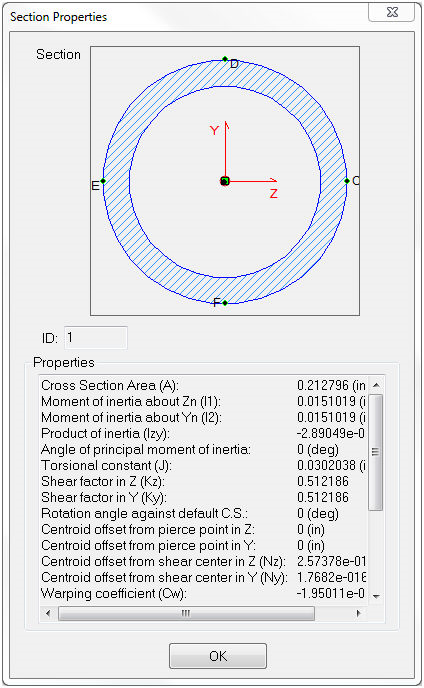
- The general cross section information (Area, Izz, Iyy, etc.) will be filled in under the Properties section once the cross section is fully defined and valid.
- NSM: A non-structural mass for the line elements will be used in calculations.
- Preload: Defines an axial preload value (not for use in nonlinear solutions).
- Offset To: Defines an offset location and differs for
Beams and
Bars.
- Beams have three options: Shear Center (default), Centroid, and Reference Point.
- Bars have two options: Centroid and Reference Point.
- The
- Structural Member (SolidWorks versions only): This option allows you to select an existing structural member. Using the
Structural Member selection you can define a 1D element as a
PBEAM,
PBAR or
PPIPE. More information can be found in the Autodesk Nastran User’s Manual regarding significance of using a PBEAML, PBAR and PPIPE.
- The
 icon allows you to hide or show the structural members, if they exist in the model. When the structural member is visible, the button looks like this
(hide all structural members). If you click on this button, the structural member becomes hidden, and the button changes to
icon allows you to hide or show the structural members, if they exist in the model. When the structural member is visible, the button looks like this
(hide all structural members). If you click on this button, the structural member becomes hidden, and the button changes to
 (show all structural members). This is particularly useful when you have to select the end points of the structural member to apply constraints.
- This is visible in physical property dialog only when the model has structural members.
- NSM: A non-structural mass for the line elements will be used in calculations.
- Preload: Defines an axial preload value (not for use in nonlinear solutions).
- Offset To: Defines an offset location and differs for
Beams and
Bars.
- Beams have three options: Shear Center (default), Centroid, and Origin.
- Bars have two options: Origin and Centroid.
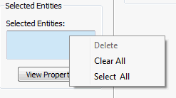
- Right-click on
Selected Entities selection box and click
Select All. It allows you to select all the structural members in the model.
- The
 button brings up the cross section definition window. This is where the cross sectional properties for a Bar, Beam or Pipe element are shown.
- The general shape of the cross section is selected by using the structural members defined using Weldments (angle iron, c chan, pipe, etc.).
- The general cross section information (Area, Iz, Iy, etc.) will be filled in under the Properties section for the selected structural member type.
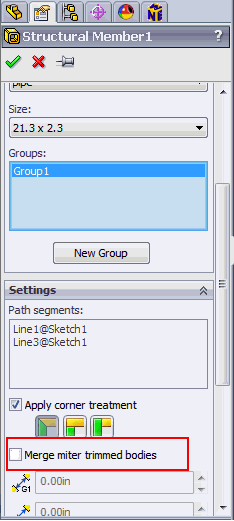
- Merge miter trimmed bodies option is currently not supported in this version. Make sure it is unchecked.
- The