Note: Tag formats can include properties that acquire their values from other properties. If the Unit value at the project level changes, all tags with that property as a subpart are updated to reflect that change.
Note: Although pipe line groups are not physical entities, you set up tag formatting for pipe line groups just as you would for any other component.
- On the ribbon, click Home tab
 Project panel
  Project Manager
  Project Setup.
 - In the Project Setup tree view, expand Plant 3D DWG Settings.
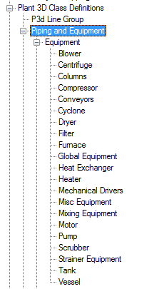
- Continue to expand the list until you locate and click a Plant 3D object (for example: Compressor).
- On the Class Settings pane, under Tag Format, click the tag format type on which you want to base the new tag format (for example: Equipment Tag [Type-Number]). Click New.
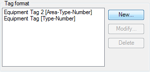
- In the Tag Format Setup dialog box, in the Format Name box, enter the name of the new format (for example: Equipment Tag [type-number] New).
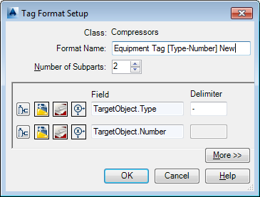
- In the Number of Subparts box, enter a number for how many subparts you want in the tag (for example: 3) or click the Up or Down arrow until the number is displayed. Tip: Use as many properties as subparts as needed. Use delimiters only between these subparts, not within them. Delimiters appear between the subparts in a tag if you place them in the Delimiter box. Entering a dash between items in the Field box (for example, N-N-N) can produce unexpected results.
-
 In the first row of icons, click Select Class Properties (the first icon on the left).
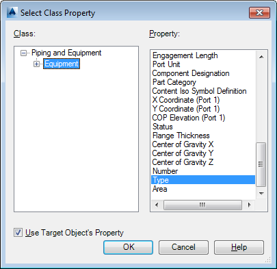
 - In the Select Class Property dialog box, do the following:
- Under Class, click Equipment.
- Under Property, click Type.
- Select the check box for Use Target Object’s Property.
- Click OK.
-
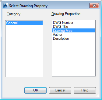
 In the Tag Format Setup dialog box, in the second row of icons, click Select Drawing Properties.
 - In the Select Drawing Property dialog box, do the following:
- Under Category, click General.
- Under Drawing Properties, click Drawing Area.
- Click OK.
-
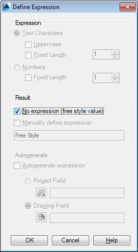
 In the Tag Format Setup dialog box, in the second row of icons, click Define Expression (the last icon in the row).
 - In the Define Expression dialog box, under Results, click No Expression (Free Style Value). Click OK.
-
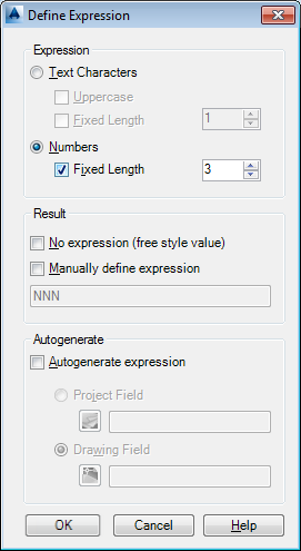
 In the Tag Format Setup dialog box, in the third row of icons, click Define Expression.
 - In the Define Expression dialog box, under Expression, do the following:
- Click Numbers.
- Select the Fixed Length check box. In the Fixed Length box, enter a number or click the Up arrow until the number is displayed.
Note:If the Expression section is disabled: under Result, clear the check box for No Expression (Free Style Value). Then follow the directions in step 14.
- Click OK.
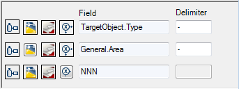
- In the Tag Format dialog box, under Delimiter, enter a delimiter where appropriate. In the example below, a period (.) is used as the delimiter for General.Area[]. Note:
Do not place a delimiter in the Field box.
- Click OK.
- On the Class Settings pane, under Properties, in the Property Name column, click TagFormatName.
- In the TagFormatName row, in the Default Value column, in the drop-down list, click the tag format you want to use for tagging the Plant 3D object.
- Click OK.
You created a new tag format and assigned it to a Plant 3D object. When you use the Plant 3D object in a drawing, the Assign Tag dialog box prompts you to enter tag data for the tag format you created in this procedure.