Geometry Helper Classes
Several Geometry Helper classes are in the API. The Helper classes are used to describe geometry information for certain elements, such as defining a CropBox for a view using the BoundingBoxXYZ class.
-
BoundingBoxXYZ - A 3D rectangular box used in cases such as defining a 3D view section area.
-
Transform - Transforming the affine 3D space.
-
Reference - A stable reference to a geometric object in a Revit model, which is used when creating elements like dimensions.
-
Plane - A flat surface in geometry.
-
Options - User preferences for parsing geometry.
-
XYZ - Object representing coordinates in 3D space.
-
UV - Object representing coordinates in 2D space.
-
BoundingBoxUV - A 2D rectangle parallel to the coordinate axes.
Transform
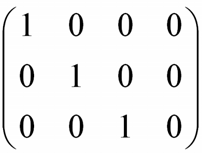
Transforms are limited to 3x4 transformations (Matrix) in the Revit application, transforming an object's place in the model space relative to the rest of the model space and other objects. The transforms are built from the position and orientation in the model space. Three direction Vectors (BasisX, BasisY and BasisZ properties) and Origin point provide all of the transform information. The matrix formed by the four values is as follows:

Applying the transformation to the point is as follows:

The Transform OfPoint method implements the previous function.
The Geometry.Transform class properties and methods are identified in the following sections.
Identity
Transform the Identity.
CreateReflection()
Reflect a specified plane.
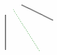
Figure 112: Wall Reflection relationship
As the previous picture shows, one wall is mirrored by a reference plane. The CreateReflection() method needs the geometry plane information for the reference plane.
|
Code Region 20-8: Using the Reflection property |
private Transform Reflect(ReferencePlane refPlane)
{
    Transform mirTrans = Transform.CreateReflection(refPlane.GetPlane());

    return mirTrans;
}
|
CreateRotation() and CreateRotationAtPoint()
Rotate by a specified angle around a specified axis at (0,0,0) or at a specified point.
CreateTranslation()
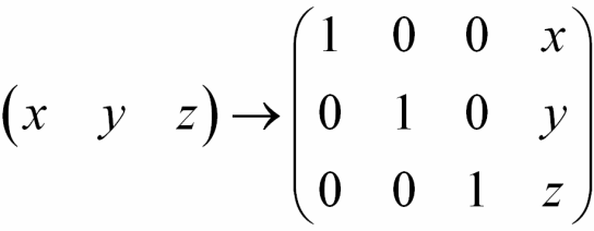
Translate by a specified vector. Given a vector XYZ data, a transformation is created as follow:
Determinant
Transformation determinant.

HasReflection
This is a Boolean value that indicates whether the transformation produces a reflection.
Scale
A value that represents the transformation scale.
Inverse
An inverse transformation. Transformation matrix A is invertible if a transformation matrix B exists such that A*B = B*A = I (identity).
IsIdentity
Boolean value that indicates whether this transformation is an identity.
IsTranslation
Boolean value that indicates whether this transformation is a translation.
Geometry.Transform provides methods to perform basal matrix operations.
Multiply
Multiplies a transformation by a specified transformation and returns the result.
Operator* - Multiplies two specified transforms.
ScaleBasis
Scales the basis vectors and returns the result.
ScaleBasisAndOrigin
Scales the basis vectors and the transformation origin returns the result.
OfPoint
Applies the transformation to the point. The Origin property is used.
OfVector
Applies the transform to the vector. The Origin property is not used.
AlmostEqual
Compares two transformations. AlmostEqual is consistent with the computation mechanism and accuracy in the Revit core code. Additionally, Equal and the == operator are not implemented in the Transform class.
The API provides several shortcuts to complete geometry transformation. The Transformed property in several geometry classes is used to do the work, as shown in the following table.
Table 48: Transformed Methods
|
Class Name |
Function Description |
|
Curve.get_Transformed(Transform transform) |
Applies the specified transformation to a curve |
|
GeometryElement.GetTransformed(Transform transform) |
Transforms a copy of the geometry in the original element. |
|
Profile.get_Transformed(Transform transform) |
Transforms the profile and returns the result. |
|
Mesh.get_Transformed(Transform transform) |
Transforms the mesh and returns the result. |
Reference
The Reference is very useful in element creation.
-
Dimension creation requires references.
-
The reference identifies a path within a geometric representation tree in a flexible manner.
-
The tree is used to view specific geometric representation creation.
The API exposes four types of references based on different Pick pointer types. They are retrieved from the API in different ways:
-
For Point - Curve.GetEndPointReference method
-
For Curve (Line, Arc, and etc.) - Curve.Reference property
-
For Face - Face.Reference property
-
For Cut Edge - Edge.Reference property
Different reference types cannot be used arbitrarily. For example:
-
The NewLineBoundaryConditions() method requires a reference for Line
-
The NewAreaBoundaryConditions() method requires a reference for Face
-
The NewPointBoundaryConditions() method requires a reference for Point.
Options
Geometry is typically extracted from the indexed property Element.Geometry. The original geometry of a beam, column or brace, before the instance is modified by joins, cuts, coping, extensions, or other post-processing, can be extracted using the FamilyInstance.GetOriginalGeometry() method. Both Element.Geometry and FamilyInstance.GetOriginalGeometry() accept an options class which you must supply. The options class customizes the type of output you receive based on its properties:
-
ComputeReferences - Indicates whether to compute the geometry reference when retrieving geometry information. The default value is false, so if this property is not set to true, the reference will not be accessible.
-
IncludeNonVisibleObjects - Indicates to also return geometry objects which are not visible in a default view.
-
View - Gets geometry information from a specific view. Note that if a view is assigned, the detail level for this view will be used in place of "DetailLevel".
-
DetailLevel - Indicates the preferred detail level. The default is Medium.
ComputeReferences
If you set this property to false, the API does not compute a geometry reference. All Reference properties retrieved from the geometry tree return nothing. For more details about references, refer to the Reference section. This option cannot be set to true when used with FamilyInstance.GetOriginalGeometry().
IncludeNonVisibleObjects
Most of the non-visible geometry is construction and conditional geometry that the user sees when editing the element (i.e., the center plane of a window family instance). The default for this property is false. However, some of this conditionally visible geometry represents real-world objects, such as insulation surrounding ducts in Revit MEP, and it should be extracted.
View
If users set the View property to a different view, the retrieved geometry information can be different. Review the following examples for more information:
-
In Revit, draw a stair in 3D view then select the Crop Region, Crop Region Visible, and Section Box properties in the 3D view. In the Crop Region, modify the section box in the 3D view to display a portion of the stair. If you get the geometry information for the stair using the API and set the 3D view as the Options.View property, only a part of the stair geometry can be retrieved. The following pictures show the stair in the Revit application (left) and one drawn with the API (right).
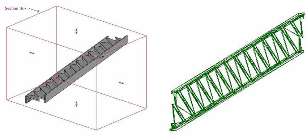
Figure 113: Different section boxes display different geometry
Draw a stair in Revit then draw a section as shown in the left picture. If you get the information for this stair using the API and set this section view as the Options.View property, only a part of the stair geometry can be retrieved. The stair drawn with the API is shown in the right picture.
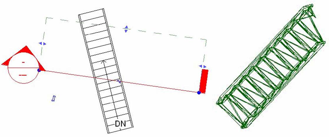
Figure 114: Retrieve Geometry section view
DetailLevel
The API defines three enumerations in Geometry.Options.DetailLevels. The three enumerations correspond to the three Detail Levels in the Revit application, shown as follows.
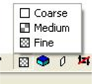
Figure 115: Three detail levels
Different geometry information is retrieved based on different settings in the DetailLevel property. For example, draw a beam in the Revit application then get the geometry from the beam using the API to draw it. The following pictures show the drawing results:
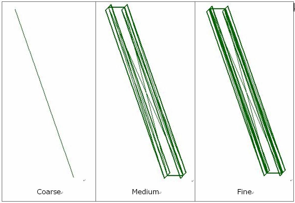
Figure 116: Detail geometry for a beam
BoundingBoxXYZ
BoundingBoxXYZ defines a 3D rectangular box that is required to be parallel to any coordinate axis. Similar to the Instance class, the BoundingBoxXYZ stores data in the local coordinate space. It has a Transform property that transforms the data from the box local coordinate space to the model space. In other words, to get the box boundary in the model space (the same one in Revit), transform each data member using the Transform property. The following sections illustrate how to use BoundingBoxXYZ.
Define the View Boundaries
BoundingBoxXYZ can be used to define the view boundaries through View.CropBox property. The following pictures use a section view to show how BoundingBoxXYZ is used in the Revit application.
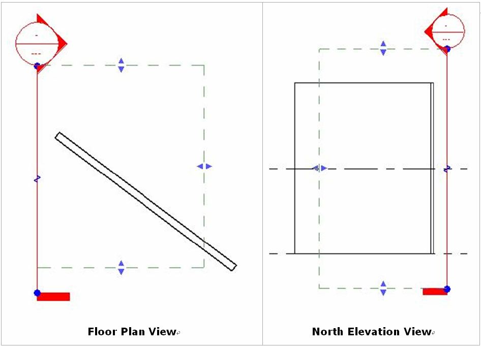
Figure 117: BoundingBoxXYZ in section view
The dash lines in the previous pictures show the section view boundary exposed as the CropBox property (a BoundingBoxXYZ instance).
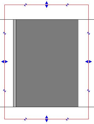
Figure 118: Created section view
The previous picture displays the corresponding section view. The wall outside the view boundary is not displayed.
Define a Section Box
BoundingBoxXYZ is also used to define a section box for a 3D view retrieved from the View3D.GetSectionBox() method. Select the Section Box property in the Properties Dialog box. The section box is shown as follows:
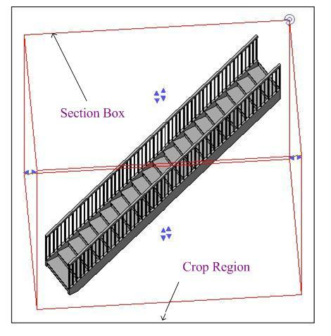
Figure 119: 3D view section box
Other Uses
-
Defines a box around an element's geometry. (Element.BoundingBox Property). The BoundingBoxXYZ instance retrieved in this way is parallel to the coordinate axes.
-
Used in the ViewSection.CreateDetail () method .
The following table identifies the main uses for this class.
Table 49: BoundingBoxXYZ properties
|
Property Name |
Usage |
||||
|
Max/Min |
Maximum/Minimum coordinates. These two properties define a 3D box parallel to any coordinate axis. The Transform property provides a transform matrix that can transform the box to the appropriate position. |
||||
|
Transform |
Transform from the box coordinate space to the model space. |
||||
|
Enabled |
Indicates whether the bounding box is turned on. |
||||
|
MaxEnabled/ MinEnabled |
Defines whether the maximum/minimum bound is active for a given dimension.
|
||||
|
Bounds |
Wrapper for the Max/Min properties. |
||||
|
BoundEnabled |
Wrapper for the MaxEnabled/MinEnabled properties. |
The following code sample illustrates how to rotate BoundingBoxXYZ to modify the 3D view section box.
|
Code Region 20-9: Rotating BoundingBoxXYZ |
private void RotateBoundingBox(View3D view3d)
{
    if (!view3d.IsSectionBoxActive)
    {
        TaskDialog.Show("Revit","The section box for View3D isn't active.");
        return;
    }
    BoundingBoxXYZ box = view3d.GetSectionBox();

    // Create a rotation transform to apply to the section box
    XYZ origin = new XYZ(0, 0, 0);
    XYZ axis = new XYZ(0, 0, 1);

    // Rotate 30 degrees
    Transform rotate = Transform.CreateRotationAtPoint(axis, Math.PI/6.0, origin);

    // Transform the View3D's section box with the rotation transform
    box.Transform = box.Transform.Multiply(rotate);

    // Set the section box back to the view (requires an open transaction)
    view3d.SetSectionBox(box);
}
|
BoundingBoxUV
BoundingBoxUV is a value class that defines a 2D rectangle parallel to the coordinate axes. It supports the Min and Max data members. Together they define the BoundingBoxUV's boundary. BoundingBoxUV is retrieved from the View.Outline property which is the boundary view in the paper space view.
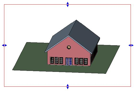
Figure 120: View outline
Two points define a BoundingBoxUV.
-
Min point - The bottom-left endpoint.
-
Max point - The upper-right endpoint.
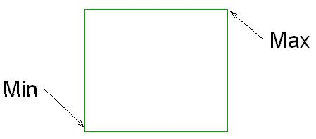
Figure 121: BoundingBoxUV Max and Min
Figure 122: Gradient rectangle

