Family Creation
When creating mechanical equipment in a Revit family document, you will need to add connectors to allow the equipment to connect to a system. Duct, electrical and pipe connectors can all be added similarly, using a reference plane where the connector will be placed and a system type for the connector.
The overloaded static methods provided by the ConnectorElement class are:
- CreateCableTrayConnector
- CreateConduitConnector
- CreateDuctConnector
- CreateElectricalConnector
- CreatePipeConnector
Each of the methods above has a second overload that takes an additional Edge parameter that allows creation of connector elements centered on internal loops of a given face. The following code demonstrates how to add two pipe connectors to faces on an extrusion and set some properties on them.
|
Code Region 30-6: Adding a pipe connector |
public void CreatePipeConnectors(UIDocument uiDocument, Extrusion extrusion)
{
        // get the faces of the extrusion
        Options geoOptions = uiDocument.Document.Application.Create.NewGeometryOptions();
        geoOptions.View = uiDocument.Document.ActiveView;
        geoOptions.ComputeReferences = true;

        List<PlanarFace> planarFaces = new List<PlanarFace>();
        Autodesk.Revit.DB.GeometryElement geoElement = extrusion.get_Geometry(geoOptions);
        foreach (GeometryObject geoObject in geoElement)
        {
                Solid geoSolid = geoObject as Solid;
                if (null != geoSolid)
                {
                        foreach (Face geoFace in geoSolid.Faces)
                        {
                                if (geoFace is PlanarFace)
                                {
                                        planarFaces.Add(geoFace as PlanarFace);
                                }
                        }
                }
        }

        if (planarFaces.Count > 1)
        {
                // Create the Supply Hydronic pipe connector
                ConnectorElement connSupply = ConnectorElement.CreatePipeConnector(uiDocument.Document,
                                                                                   PipeSystemType.SupplyHydronic,
                                                                                   planarFaces[0].Reference);
                Parameter param = connSupply.get_Parameter(BuiltInParameter.CONNECTOR_RADIUS);
                param.Set(1.0); // 1' radius
                param = connSupply.get_Parameter(BuiltInParameter.RBS_PIPE_FLOW_DIRECTION_PARAM);
                param.Set(2);

                // Create the Return Hydronic pipe connector
                ConnectorElement connReturn =  ConnectorElement.CreatePipeConnector(uiDocument.Document,
                                                                                    PipeSystemType.ReturnHydronic,
                                                                                    planarFaces[1].Reference);
                param = connReturn.get_Parameter(BuiltInParameter.CONNECTOR_RADIUS);
                param.Set(0.5); // 6" radius
                param = connReturn.get_Parameter(BuiltInParameter.RBS_PIPE_FLOW_DIRECTION_PARAM);
                param.Set(1);
        }
}
|
The following illustrates the result of running this example using in a new family document created using a Mechanical Equipment template and passing in an extrusion 2'×2'×1'. Note that the connectors are placed at the centroid of the planar faces.
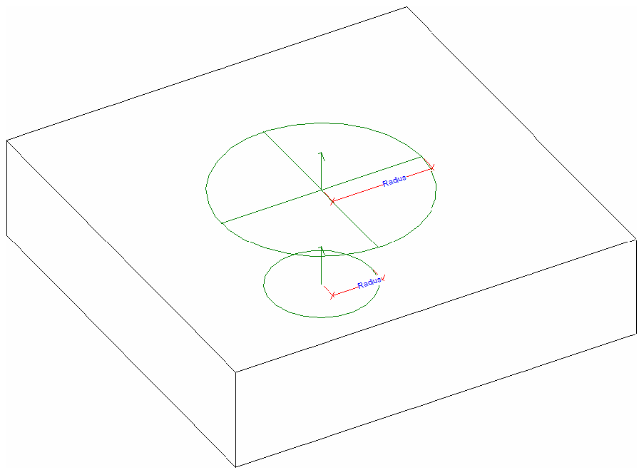
Figure 169: Two connectors created on an extrusion