In Revit Structure, an analytical model is the engineering description of a structural physical model.
The following structural elements have structural member analytical models:
- Structural Columns
- Structural Framing elements (such as beams and braces)
- Structural Floors
- Structural Footings
- Structural Walls
An Element's AnalyticalModel can be obtained using the GetAnalyticalModel() method. Note that the AnalyticalModel for a newly created structural element is not available until a Regeneration occurs. Depending on the element's family, the AnalyticalModel may not exist. If the AnalyticalModel value does not apply to an element's family, the GetAnalyticalModel() method returns null. Check the value before using this class. AnalyticalModel is made up of the following information:
- Location of the Element with respect to analysis
- Parameter Information, including projection, hard points, approximation, and rigid links
- Support Information
- Adjustment Information, both Manual and Automatic
- Analytical Offset
Specific options are available in specialized classes:
- AnalyticalModelStick - represents analytical model for Structural Framing Beams, Structural Framing Braces and Structural Columns.
- AnalyticalModelColumn - subclass of AnalyticalModelStick, represents an analytical model for a Structural Column.
- AnalyticalModelSurface - represents analytical model for Structural Floor, Structural Foundation Slab and Structural Wall.
Analytical Location
Depending on the type of element that corresponds to the AnalyticalModel, the location of the element with respect to analysis can be obtained by one of three methods: GetPoint(), GetCurve() or GetCurves().
Note that the curves retrieved from these methods do not have their Reference properties set. Therefore, they cannot be used for methods such as Curve.GetEndPointReference(). Instead, you can obtain References to the curves and their end points through construction of an AnalyticalModelSelector object containing the necessary information, as the following example demonstrates.
|
Code Region 29-10: Getting a reference to analytical curve |
public bool GetReferenceData(FamilyInstance familyInst)
{
        AnalyticalModel analyticalModelFrame = familyInst.GetAnalyticalModel();
        Curve analyticalCurve = analyticalModelFrame.GetCurve();
        if (null != analyticalCurve)
        {
                // test the stable reference to the curve.
                AnalyticalModelSelector amSelector = new AnalyticalModelSelector(analyticalCurve);
                amSelector.CurveSelector = AnalyticalCurveSelector.WholeCurve;
                Reference curveReference = analyticalModelFrame.GetReference(amSelector);

                // test the stable reference to the start point of the curve
                amSelector.CurveSelector = AnalyticalCurveSelector.StartPoint;
                Reference startPointReference = analyticalModelFrame.GetReference(amSelector);

                // test the stable reference to the start point of the curve
                amSelector.CurveSelector = AnalyticalCurveSelector.EndPoint;
                Reference endPointReference = analyticalModelFrame.GetReference(amSelector);
        }

        return true;
}
|
GetPoint()
If the AnalyticalModel can be expressed by a single point (i.e. Structural Footing), this method will return that point. Otherwise, it will throw an Autodesk.Revit.Exceptions.InapplicableDataException. The IsSinglePoint() method can be used to determine if the AnalyticalModel can be expressed by a single point.
The following example demonstrates how to get the analytical location for a structural footing.
|
Code Region 29-11: Getting the location for a structural footing |
// retrieve and iterate current selected element
UIDocument uidoc = commandData.Application.ActiveUIDocument;
ElementSet selection = uidoc.Selection.Elements;
foreach (Element e in selection)
{
        // if the element is structural footing
        FamilyInstance familyInst = e as FamilyInstance;
        if (null != familyInst && familyInst.StructuralType == StructuralType.Footing)
        {
                AnalyticalModel model = familyInst.GetAnalyticalModel();
                // structural footing should be expressable as a single point
                if (model.IsSinglePoint() == true)
                {
                        XYZ analyticalLocationPoint = model.GetPoint();
                }
        }
}
|
GetCurve()
If the AnalyticalModel can be expressed by a single curve (i.e. Structural Column or Structural Framing), this method will return that Curve. Otherwise, it will throw an Autodesk.Revit.Exceptions.InapplicableDataException. The IsSingleCurve() method can be used to determine if the AnalyticalModel can be expressed by a single curve.
|
Code Region 29-12: Getting the curve for a structural column |
public void GetColumnCurve(FamilyInstance familyInst)
{
        // get AnalyticalModel from structural column
        if (familyInst.StructuralType == StructuralType.Column)
        {
                AnalyticalModel modelColumn = familyInst.GetAnalyticalModel();
                // column should be represented by a single curve
                if (modelColumn.IsSingleCurve() == true)
                {
                        Curve columnCurve = modelColumn.GetCurve();
                }
        }
}
|
GetCurves()
This method is required to get the Curves of an AnalyticalModel defined by more than one curve, but can be used in all cases. If the AnalyticalModel can be expressed by a single curve, this method will return a List containing only one Curve. If the AnalyticalModel can be expressed by a single point, this method will return a Curve of almost 0 length containing the point. This method takes an AnalyticalCurveType enum as a parameter. The possible values are:
- RawCurves - Base Analytical Model curves generated
- ActiveCurves - Curves displayed on screen (not including Rigid Links)
- ApproximatedCurves - Curves approximated using linear segments
The following values related to Rigid Links are also available. See the Rigid Links section later in this chapter for more information.
- RigidLinkHead - Rigid Link at end 0 (head) of the Beam
- RigidLinkTail - Rigid Link at end 1 (tail) of the Beam
- AllRigidLinks - All Rigid Link curves. Rigid Link at end 0 (head) will be in the first entry. Rigid Link at end 1 (tail) will be in the last entry.
GetLoops()
- All - All analytical loops
- External - Loop outside all other loops.
- Internal - Loop that is inside another loop. In the case of multiple nested loops, this will return all loops except the most external loop.
- Filled - Loops that are filled inside. In the case of multiple nested loops, this will return the most external and every second loop going from external to internal. In the view, returned loops are presented as external outline of solids.
- Void - Loops that are empty inside. In the case of multiple nested loops, this will return a series of loops starting from second most external and every second heading into the most internal. In the view returned loops are presented as external outline of openings.
The following example demonstrates the use of AnalyticalModelSurface for structural walls to get the outer edges of all selected walls and display their coordinates.
|
Code Region 29-13: Getting the curves for a structural wall |
// retrieve and iterate current selected element
UIDocument uidoc = commandData.Application.ActiveUIDocument;
ICollection<ElementId> selectedIds = uidoc.Selection.GetElementIds();
Document document = uidoc.Document;
foreach (ElementId id in selectedIds)
{
    Element e = document.GetElement(id);
    Wall aWall = e as Wall;
    if (null != aWall)
    {
        // get AnalyticalModelSurface from Structural Wall
        AnalyticalModelSurface modelWall = aWall.GetAnalyticalModel() as AnalyticalModelSurface;
        if (null == modelWall)
        {
            // Architecture wall doesn't have analytical model
            continue;
        }

        // get wall curves
        StringBuilder wallString = new StringBuilder();
        wallString.AppendLine("Wall curves:");
        IList<CurveLoop> wallCurveLoops = modelWall.GetLoops(AnalyticalLoopType.External);
        foreach (CurveLoop curveloop in wallCurveLoops)
        {
            CurveLoopIterator itr = curveloop.GetCurveLoopIterator();
            itr.Reset();
            while (itr.MoveNext())
            {
                Curve wallCurve = itr.Current;
                wallString.AppendLine(String.Format("{0}, {1}", wallCurve.GetEndPoint(0).ToString(), wallCurve.GetEndPoint(1).ToString()));
            }
        }

        TaskDialog.Show("Wall Analytical Model", wallString.ToString());
    }
}
|
Local Coordinate System
Orientation of the local coordinate systems of AnalyticalModelStick and AnalyticalModelSurface elements can be obtained as a transform by calling the overloaded GetLocalCoordinateSystem() method. For AnalyticalModelSurface, the overload of this method that takes no parameters will return the transform for the orientation of the local coordinate system for the overall model while the overload that takes an XYZ point will return the transform which describes the local coordinate system at the specified point on the surface. The point specified must be on the surface of the analytical model or Revit will throw an exception.
When calling GetLocalCoordinateSystem() on the AnalyticalModelStick class you may optionally call GetLocalCoordinateSystem(double) passing a distance along the curve represented by a parameter which may vary between 0 and 1 (e.g., 0.5 represents the halfway point along the parameterized curve). You may also call GetLocalCoordinateSystem(XYZ point) with the same constraints as when this is called on AnalyticalModelSurface in that the point specified must lie along the analytical model.Face.Evaluate or Curve.Evaluate may be used to obtain XYZ points which lie on either the surface or along the curve.
Parameter Information
AnalyticalModel provides access to Parameter information such as rigid links, projection, and approximation.
Rigid Links
A rigid link connects the analytical model of a beam to the analytical model of a column. Use the CanHaveRigidLinks()method and the AnalyticalModel.RigidLinksOption property to determine if rigid links are applicable to the AnalyticalModel. Additionally, you can use HasRigidLinksWith() to determine whether the AnalyticalModel has rigid links with a specific element.
End links can be retrieved by specifying the AnalyticalCurveType options RigidLinkHead and RigidLinkTail with the AnalyticalModel.GetCurves() Method. Or, use AnalyticalModel.GetRigidLink() with an AnalyticalModelSelector object.
One difference between the AnalyticalModel methods GetCurve() and GetCurves() for a structural beam is that GetCurves() includes the single Curve as well as the structural beam RigidLink Curve if it is present. Pass the AnalyticalCurveType.RigidLinkHead or AnalyticalCurveType.RigidLinkTail enum values to the GetCurves() method to get the RigidLink at the head or tail of a beam.
Although you cannot create a rigid link directly since it is not an independent object, you can create it using the RigidLinksOption property on the analytical model for beams and/or columns. The rigid link option for a beam overrides the option for the column.
For Structural Beams, the RigidLinksOption property can have the following values:
- AnalyticalRigidLinksOption.Enabled - Rigid links will be formed
- AnalyticalRigidLinksOption.Disabled - Rigid links will not be formed
- AnalyticalRigidLinksOption.FromColumn - Rigid links may be formed, depending on the corresponding structural column's value.
For Structural Columns, the RigidLinksOption property can have the following values:
- AnalyticalRigidLinksOption.Enabled - Rigid links will be formed, unless corresponding structural beam's setting overrides.
- AnalyticalRigidLinksOption.Disabled - Rigid links will not be formed, unless corresponding structural beam's setting overrides.
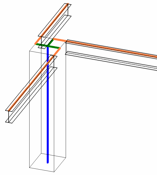
Figure 159: RigidLink
Alignment, projection and extension
| Code Region: Change AnalyticalModelStick projection |
|---|
public void ChangeBeamProjection(FamilyInstance familyInstance)
{
    AnalyticalModelStick ams = familyInstance.GetAnalyticalModel() as AnalyticalModelStick;
    if (ams != null)
    {
        // Change the Z projection for the end of the beam
        StickElementProjectionZ orgEndProj = ams.GetProjectionZ(AnalyticalElementSelector.EndOrTop);
        StickElementProjectionZ newEndProj = StickElementProjectionZ.Bottom;
        using (Transaction tran = new Transaction(familyInstance.Document, "ChangeProjection"))
        {
            tran.Start();
            ams.SetProjection(AnalyticalElementSelector.EndOrTop, ElementId.InvalidElementId, newEndProj);
            tran.Commit();
        }

        TaskDialog.Show("AnalyticalModelStick", "AnalyticalModelStick ID: " + ams.Id + "; \nOriginal ProjectionZ value was: " + orgEndProj + "; \nNew ProjectionZ value: " + newEndProj);
    }
}
|
| Code Region: Change AnalyticalModelSurface projection |
|---|
/// <summary>
/// Change the Z projection for all surface elements to BottomOrExterior
/// </summary>
public void ChangeSurfaceProjections(Document document)
{
    FilteredElementCollector collector = new FilteredElementCollector(document);
    IList<Element> elements = collector.WherePasses(new ElementClassFilter(typeof(AnalyticalModelSurface))).WhereElementIsNotElementType().ToElements();
    if (elements.Count > 0)
    {
        using (Transaction tran = new Transaction(document, "Change Surface Projections"))
        {
            tran.Start();
            foreach (AnalyticalModelSurface ams in elements)
            {
                SurfaceElementProjectionZ orgEndProj = ams.ProjectionZ;
                SurfaceElementProjectionZ newEndProj = SurfaceElementProjectionZ.BottomOrExterior;
                ams.ProjectionZ = newEndProj;
            }
            tran.Commit();
        }
    }
}
|
| Code Region: Set TopExtension for column |
|---|
/// <summary>
/// Change the top extension for the column to Reference Level
/// </summary>
public void ChangeColumnTopExtension(FamilyInstance column)
{
    AnalyticalModelColumn amc = column.GetAnalyticalModel() as AnalyticalModelColumn;
    if (amc != null)
    {
        using (Transaction tran = new Transaction(column.Document, "Change Top Extension"))
        {
            tran.Start();

            StickElementExtension orgTopExt = amc.TopExtension;
            StickElementExtension newTopExt = StickElementExtension.ReferenceLevel;
            amc.TopExtension = newTopExt;

            TaskDialog.Show("AnalyticalModelColumn", "AnalyticalModelColumn ID: " + amc.Id + "; \nOriginal TopExtension value was: " + orgTopExt + "; \nNew TopExtension value: " + newTopExt);

            tran.Commit();
        }
    }
}
|
Approximation
When an AnalyticalModel is defined by a curve rather than a straight line (i.e. for a curved beam), an approximation (comprised of straight lines) may be preferable. AnalyticalModel has several methods related to curve approximation. If CanApproximate() returns true, use the Approximate() method to switch between non-approximated (curved) Analytical Models and approximated (made up of lines only) Analytical Models. After switching to approximated, use GetCurves() to get the lines of the approximated curve.
The approximation will be based on the approximation deviation value (GetApproximationDeviation()) and the Use Hard-points parameter (UsesHardPoints()). These values have corresponding Set methods as well. The approximation deviation limits the distance between the smooth curve and a line segment generated by an approximation. Hard-points are the locations on the curved beam where other structural elements are touching. When you set this parameter to true, it forces the segmented analytical model to have nodal points at the ends of the members attached to the curved beam
AnalyzeAs
The Analyze As parameter can be retrieved and set via the AnalyticalModel. This parameter indicates to analysis programs how an element should be analyzed, or whether the element is NotForAnalysis. Since the AnalyzeAs enum used by GetAnalyzeAs() and SetAnalyzeAs() contains enum values used for different types of elements, not all values are applicable for all analytical models. Use the IsAnalyzeAsValid() method to determine if a particular value is applicable for the analytical model.
Manual Adjustment
The geometry of the structural member analytical model may also be adjusted in relation to those elements to which it joins (assuming the SupportsManualAdjustment() method returns true). Use the AnalyticalModel.ManuallyAdjust() method to adjust the analytical model in relation to another element.
|
Code Region 29-14: Adjusting the analytical model in relation to another element |
// Pick the source analytical line to adjust to
Selection sel = app.ActiveUIDocument.Selection;
Reference refAnalytical = sel.PickObject(ObjectType.Element, "Please Pick the source analytical line to adjust to");
AnalyticalModel aModel = doc.GetElement(refAnalytical) as AnalyticalModel;
Curve aCurve = aModel.GetCurve();

// Get the reference of the start point
AnalyticalModelSelector aSelector = new AnalyticalModelSelector(aCurve);
aSelector.CurveSelector = AnalyticalCurveSelector.StartPoint;
Reference refSource = aModel.GetReference(aSelector);

// Pick the source analytical line to be adjusted
Reference refAnalytical2 = sel.PickObject(ObjectType.Element, "Please pick the source analytical line to be adjusted");
AnalyticalModel aModel2 = doc.GetElement(refAnalytical2) as AnalyticalModel;

// Get the reference of the start point
Curve aCurve2 = aModel2.GetCurve();
AnalyticalModelSelector aSelector2 = new AnalyticalModelSelector(aCurve2);
aSelector2.CurveSelector = AnalyticalCurveSelector.StartPoint;
// Can be adjusted to the middle of the line if WholeCurve is used
Reference refTarget = aModel2.GetReference(aSelector2);

// Adjust the analytical line
aModel.ManuallyAdjust(refSource, refTarget, true);
|
AnalyticalModel also provides methods to determine if the analytical model has been manually adjusted and to reset it back to its original location, relative to its corresponding physical model. Additionally, the GetManualAdjustmentMatchedElements() method retrieves a collection of element Ids against which the Analytical Model has been adjusted.
Analytical Offset
Another way to adjust an analytical model is to use an offset. Setting the analytical offset is different than manually adjusting the analytical model. The analytical offset is a basic offset applied to the entire analytical model and is independent of any other elements. AnalyticalModel has methods to get and set the analytical offset as well as to determine if the analytical offset can be changed (CanSetAnalyticalOffset()).
AnalyticalModelSupport
AnalyticalModel provides the method IsElementFullySupported() to determine if the analytical model is fully supported. For additional information about what is supporting the analytical model, the GetAnalyticalModelSupports() method retrieves a collection of AnalyticalModelSupport objects that provide information on how the element is supported by other structural elements, including the priority of each support (if multiple elements provide support) and the point, curve or face that provides the support. The following examples illustrate how to use the AnalyticalModelSupport objects in different conditions.
Floor and StructuralBeam Support Information
When drawing a slab in sketch mode, select Pick Supports on the design bar. As shown in the following picture, a slab has three support beams. By iterating the slab's collection of AnalyticalModelSupports, you get the three Beams as well as the CurveSupport AnalyticalSupportType.
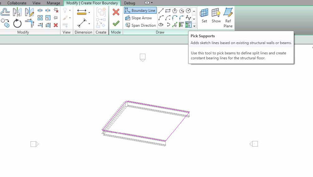
Figure 160: Floor and StructuralBeam Support Information
Floor and Wall Support Information
After drawing a slab by picking walls as the support, you cannot get Walls from the Floor's AnalyticalModelSupport collection. Instead, Floor is available in the Wall's collection of AnalyticalModelSupports.
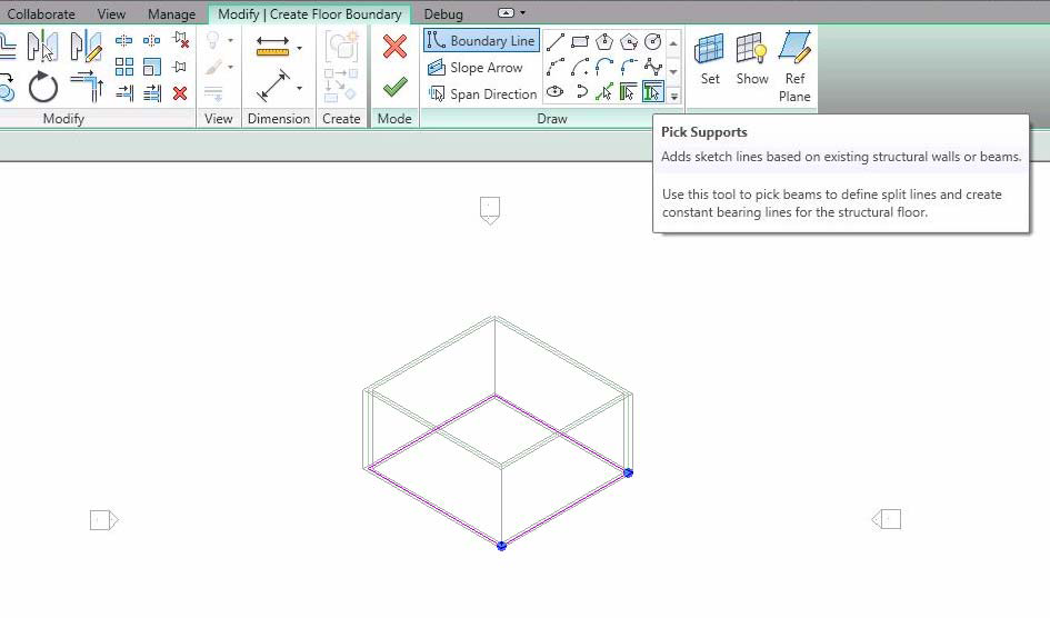
Figure 161: Floor and Wall Support Information
Structural Column, Beam and Brace Support Information
In the following picture, the horizontal beam has three PointSupports--two structural columns and one structural brace. The brace has three PointSupports-- two structural columns and one structural beam. Neither column has a support Element.
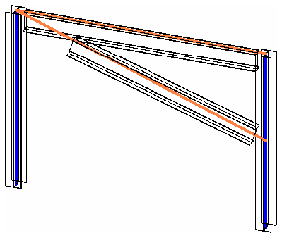
Figure 162: StructuralElements Support Information
BeamSystem and Wall Support Information
Though you can pick walls as supports when you draw a BeamSystem, its support information is not directly available because the BeamSystem does not have the AnalyticalModel property. The solution is to call the GetBeamIds() method, to retrieve the AnalyticalModelSupport collection for the Beams.
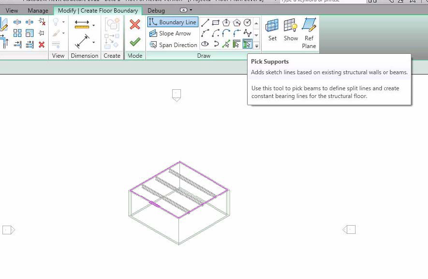
Figure 163: BeamSystem and Wall Support Information
WallFoundation and Wall Support Information
For a Wall with a wall foundation, the Wall has a CurveSupport with WallFoundation available. The support curves are available using the AnalyticalModel.GetCurves() method. In the following sample, there are two Arcs in the Curve.
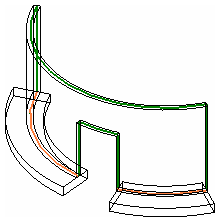
Figure 164: WallFoundation and Wall Support Information
Isolated Foundation and StructuralColumn Support Information
Structural columns can have an isolated footing as a PointSupport. In this condition, the footing can move with the supported structural column. The ElementId of the FamilyInstance with the OST_StructuralFoundation category is available from the AnalyticalModelSupport.GetSupportingElement() method. Generally, the support point is the bottom point of the curve retrieved from the AnalyticalModel.GetCurve() method. It is also available after you get the isolated footing FamilyInstance and the AnalyticalModel Point available from the GetPoint() method.
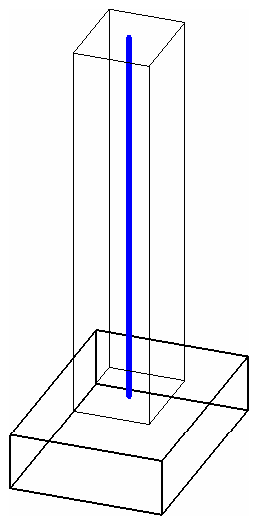
Figure 165: Isolated Foundation (FamilyInstance) and Structural Column Support Information
Analytical member forces
The AnalyticalModelStick class can store six internal forces at each end of the stick element. At each end 3 translational forces and 3 rotational (moment) forces may be stored. These member forces may represent the result of a particular set of loads on the model or may represent the design forces for use in connection design. There is no association with load cases or combinations. The member forces correspond to the Member Forces property of the UI for analytical stick models (found on beams, braces, and columns).
These forces are represented by the MemberForces class which provides access to get and set all 6 force components (3 forces, 3 moments) and provides an indication of whether the object represents forces at the member start or the member end through the Start property: set to true for start end forces and false for end forces.
Both start and end forces and moments are stored as an XYZ vector composed of the component values of the forces or moments. E.g., Forces.X represents the value of the force acting in the X direction.
Reading member forces
You may access the member forces stored with the analytical model by calling the method AnalyticalModelStick.GetMemberForces() which returns a list of MemberForces objects with a minimum count of zero and a maximum count of 2 (one for each end). If no member forces are stored for the member, the list will be empty, if only one end has forces specified, then the list will only contain one MemberForces object. Note that any force or moment directions which are set to "Released" in the UI or set to true (released) via AnalyticalModelStick.SetReleases() will be reported as 0.0 when queried via AnalyticalModleStick.GetMemberForces(). (Released forces or moments cannot resist forces or moments in those directions which are released.)
Setting member forces
Member forces may be set on an AnalyticalModelStick by calling one of the overloaded SetMemberForces() methods. SetMemberForces() will overwrite any existing member forces with the newly supplied member forces.
For any force or moment directions which are currently released, both the UI and AnalyticalModelStick.GetMemberForces() will return those as zero but if you set them though AnalyticalModelStick.SetMemberForces() method, they will be retained such that, if the user later clears the release, or you clear it through AnalyticalModelStick.SetReleases() the previously set value will then be reported.
Removing member forces
Member forces for AnalyticalModelSticks may be removed for both ends at once or only for an individual end. To remove all member forces for an element call AnalyticalModelStick.RemoveAllMemberForces(). To remove member forces only for the start or the end, call AnalyticalModelStick.RemoveMemberForces() and indicating which end to remove.