- Click
 Mesh
Mesh Mesh 3D Mesh Settings.
 - Click Options.
- Select Absolute mesh size from the Type drop-down list.
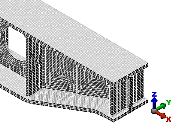
- Type 8 in the Size input field. This size results in three elements through the thickness of the top and bottom flanges, two through the gussets, and an overall high-quality surface mesh appearance.
- Click OK.
- Click Mesh model. The meshing process starts.
- Click Options.
- When asked to review the mesh results, click No. The meshed model displays as shown in the following image. Due to the fineness of the mesh, the viewpoint has been zoomed-in to show only about one-third of the model, making the mesh lines more visible.
- Use the
 View Navigate Orbit Orbit,
  View Navigate Zoom Zoom, and
  View Navigate Pan commands (or the related mouse button/wheel, ViewCube, or Navigation Bar tools) to inspect the mesh in various areas of the model.
 - Click
 Save on the Quick Access Toolbar (QAT) to save your model.
Note: Even though the default mesh type is Solid, only the surface mesh has been created at this point. By default, the generation of the interior mesh lines is postponed until the first time the Run Simulation or Check Model command is executed.
The tutorial is now complete. Use the meshed model to complete the Support Beam Static Stress Analysis and Modification using SimStudio Tools tutorial.