- Click
 Mesh
Mesh Mesh 3D Mesh Settings. The Model Mesh Settings dialog box appears
 - Click the Options button.
- Select Absolute mesh size from the Type drop-down list.
- Type 0.5 in the Size input field.
- Click OK.
- Click Mesh model. The meshing process starts.
- Click the Options button.
- When asked to review the mesh results, click No. The meshed model displays as shown in the following image.
- To better see the mesh lines, click the
 View Appearance CAD Surfaces option to turn it off. Instead of using the original CAD surfaces, the model shading is now based on the FEA mesh. Typically, this shading method improves the mesh line rendering along curved surfaces and prevents mesh lines from being hidden by the surface shading. The model should appear as shown below.
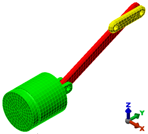
- Use the
 View Navigate Orbit Orbit,
  View Navigate ZoomZoom, and
  View Navigate Pan commands (or the related ViewCube, mouse button, or Navigation Bar tools) to inspect the mesh in various areas of the model.
Note: Even though the default mesh type is Solid, only the surface mesh has been created at this point. By default, the generation of the interior mesh lines is postponed until the first time that the Run Simulation or Check Model command is executed.