Next, divide the beam element (Part 5) into smaller increments to provide multiple results calculation points along its length.
- With
 Selection
 Select Lines still active, click near the middle of the long line spanning between the rigid element spokes to select it.
- Click
 Draw Modify Divide. The Divide Lines dialog box appears.
 - Type 12 in the Number of Lines field.
- Click OK.
- To visualize the beam divisions, click
 View Visibility Endpoint Vertices. The model appears as shown in the following image, with blue X markers at each vertex.
  Note: The resultant beam element length is 1.5 inches each when the original 18 inch long span is divided into 12 increments.
 - Click View Visibility Endpoint Vertices again to turn off the vertex markers.
- Click the
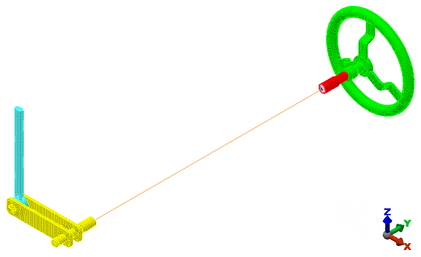
 Home icon immediately above the ViewCube for an isometric view of the model. Note: The Home icon will not be visible until the cursor is at or near the ViewCube.
The model should look like the following image:
- Click
 Save on the Quick Access Toolbar (QAT) to save your model.
This tutorial is now complete. You can use the meshed model to complete the Remote Crank Static Stress Analysis tutorial.