I. Adjust the Model Viewpoint
- On the Quick Access Toolbar (QAT), click
 Save.
Save. - Click
 Tools
Tools Edit SimStudio Tools. The solid model opens in Autodesk SimStudio Tools. Note: The named model views are different in SimStudio than in Simulation Mechanical. The default model orientation scheme is Y-up for SimStudio Tools and Z-up for Simulation Mechanical. The Front view in SimStudio Tools corresponds to the Top view in Simulation Mechanical.
 - Click near the middle of the FRONT face of the ViewCube.
- Click on the triangle below the ViewCube. The model viewpoint should correspond to the Front view in Simulation Mechanical.
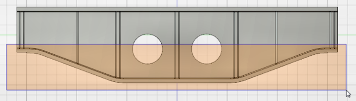
Optionally, redefine the view name to suit the model. Right-click on the ViewCube and click Set current view as
Front. The ViewCube FRONT view orientation should now match the orientation in Simulation Mechanical, and the model should look like the following image: 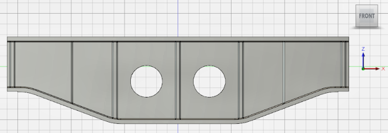 Tip: This step does not reorient the Home (isometric) view orientation. You would have to do that separately by orienting the model viewpoint to be consistent with the Simulation Mechanical Home view. Then, you would use the command, Set current view as Home Fit to View from the ViewCube context menu to reorient the Home view definition. However, it is not necessary for you to do so.
II. Increase the Support Beam Height
Now that the model viewpoint is oriented appropriately, we can increase the beam height. There are two methods to increase the beam height by 60 mm while keeping the web holes centered vertically:
- Raise the top flange 60 mm and raise the location of the holes 30 mm.
- Raise the top flange 30 mm and lower the bottom flange 30 mm.
We will use the latter method.
- Click the down-arrow at the bottom of the SELECT panel of the ribbon to expand the panel. Then...
- Click Selection Filters Select All to ensure that all types of features can be selected.
- While the pop-up list of filters is still open, ensure that the Select Through checkbox is activated. This option is necessary for hidden features on the back side of the model to be selected when enclosed in a selection rectangle.
- Click Selection Filters
- Click the down-arrow at the bottom of the MODIFY panel of the ribbon to see the available geometry modification commands. Then, click
 Move.
Move. - In the Object section of the Move dialog box, click
 Move Faces.
 - Click and drag to draw a selection window that encloses only the top flange and all of the corner chamfers on the underside of it, as shown below:
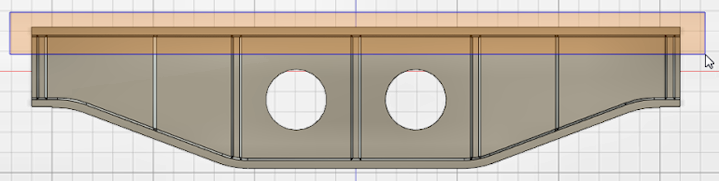
The top flange and chamfers become highlighted in blue and a pivot point and movement triad appear somewhere along the selected faces.
Note: The movement triad may or may not be oriented as needed, specifically with a vertical (preferably upward) movement vector. For example, the triad in the following image does not have a movement vector that is parallel with the global Z-axis of the CAD model, which is what we need.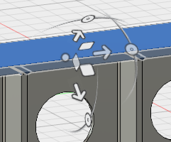
If a movement vector does not point in the +Z or -Z direction, perform the optional procedure under Step 2c below. Otherwise, skip to Step 2d.
- Optionally, to reorient the movement triad, click the
 Set Pivot icon in the Move dialog box. Then...
 - Move the cursor along the horizontal or vertical edges of the model. The pivot point and triad will follow the mouse movement and reorient as you move along the various model features.
- Click the mouse to anchor the pivot point and triad in a new, suitable location.
Alternatively, you can return to the Home dialog box, while avoiding dragging the cursor across the model geometry, which would again move the triad. Then, click the Done icon (
 ) to the right of Set Pivot to anchor the pivot point.
Here is an example of a move-triad that is suitably oriented:
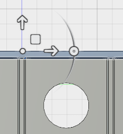
- Click the movement vector that aligns with the Z-axis and drag it upward a short distance. A Distance input field appears near the movement triad. Perform one of the following two actions, depending upon whether the vector points upward or downward:
- Vector Points in +Z (Upward) Direction: Type 30 in the distance input field and press Enter.
- Vector Points in -Z (Downward) Direction: Type –30 in the distance input field and press Enter.
- In the Object section of the Move dialog box, click
- Once again, click MODIFY Move.
- In the Object section of the Move dialog box, click Move Faces.
- Click and drag to draw a selection window that encloses only the bottom flange and all of the corner chamfers on the underside of it, as shown below. Be careful to NOT fully enclose the web holes.
 Note: Again, the movement triad may or may not be oriented as needed, specifically with a vertical (preferably downward) movement vector.
If a movement vector does not point in the -Z or +Z direction, perform the optional procedure under Step 3c below. Otherwise, skip to Step 3d.
- Optionally, to reorient the movement triad, click the Set Pivot icon in the Move dialog box. Then...
- Move the cursor along the horizontal or vertical edges of the model. The pivot point and triad will follow the mouse movement and reorient as you move along the various model features.
- Click the mouse to anchor the pivot point and triad in a new, suitable location.
Alternatively, you can return to the Home dialog box, while avoiding dragging the cursor across the model geometry, which would again move the triad. Then, click the Done icon (
) to the right of Set Pivot to anchor the pivot point.
Here is an example of a move-triad that is suitably oriented:

- Click the movement vector that aligns with the Z-axis and drag it downward a short distance. A Distance input field appears near the movement triad. Perform one of the following two actions, depending upon whether the vector points downward or upward:
- Vector Points in -Z (Downward) Direction: Type 30 in the distance input field and press Enter.
- Vector Points in +Z (Upward) Direction: Type –30 in the distance input field and press Enter.
- In the Object section of the Move dialog box, click
What Else Can I Do with SimStudio Tools?
- Push on an edge to turn it into a fillet or chamfer.
- Push or pull on existing fillets or chamfers to change their size.
- Push or pull on individual surfaces to change the thickness or shape of a structure or the diameter of a hole.
- Bend and move edges.
- Add or remove features (such as holes).
- Mirror features, create rectangular or polar patterns of features, or create a pattern of features along a specified path.
- Split surfaces, which is useful in FEA models to restrict surface loads to a portion of a larger surface.
Please consult the SimStudio Help for additional information.
III. Save the CAD Model and Pass it Back into Simulation Mechanical
Before returning to Simulation Mechanical, save the revised support beam as a SimStudio Tools file.
- On the Quick Access Toolbar (QAT), click Save. The original CAD solid model is not overwritten because it is a Step file (*.stp), whereas SimStudio Tools files have a .SimStudio extension.
- Navigate to the folder where the original support beam STEP and FEA model files reside.
- Accept the default filename of Support Beam.SimStudio and click Save.
- Click
 ADD-INS Simulate in Mechanical.
 - Click No when asked if you want to use the default Simulation Mechanical color palette instead of the CAD model colors.
- Click No when asked about importing CAD part names. The part name is already defined in the Simulation Mechanical model.
- After the model is transferred, it is automatically remeshed using the parameters specified for the original analysis. The previously defined load and constraints are still present.
- Close SimStudio Tools. We do not need to use it again for this tutorial.