The Joint Mesh Setup dialog box should still be open after creation of the previous two joints. The part number has again been incremented to the next available unused number (5). Also, the Participating surfaces list has been cleared. This time, we need the part number of the joint to differ from the previous two. In order to transmit a rotational displacement to the crank, beam elements are required for the joint. Trusses, which are specified by default for joints, transmit axial loads only.
- Deactivate the Do not dismiss dialog after joint generation option. This is the last joint we need to create.
- With the
 Selection
 Shape Circle and
  Selection Select Surfaces commands still active, draw a circle enclosing the hole at the free end of the crank as shown in the following image. The centerline of this hole is the centerline of crank rotation.
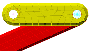
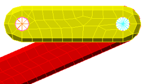
- Click Add in the Joint Mesh Setup dialog box. One surface is added to the Participating surfaces list.
- Click OK to add the pin joint and dismiss the dialog box. The model appears as shown in the following image.
- Select
 View Navigate Enclose (Fit All) (or the equivalent Navigation Bar command). The model displays as shown in the following image.
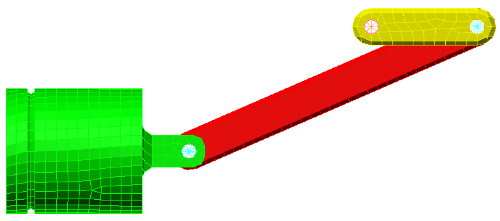
- Click
 Save on the Quick Access Toolbar (QAT) to save your model.
This tutorial is now complete. You can use this model to complete the Piston Mechanical Event Simulation tutorial.