Create a blank SimStudio Tools model and assign it a name. Define the model orientation that is consistent with Simulation Mechanical. Define the length unit. Create three blank components within the model and specify a name for each of these.
- From the Windows Start Menu, start SimStudio Tools (Start
 All Programs Autodesk Autodesk SimStudio Tools 20xx SimStudio Tools 20xx).
 - Before creating a new model, change the default model orientation in SimStudio Tools to be consistent with Simulation Mechanical, which defaults to the Z-up orientation. Click the Application Menu icon (
 ) icon at the far left end of the Quick Access Toolbar (QAT).
 - Select Preferences. The Preferences controlling general UI behavior settings are shown initially.
- Change the Default modeling orientation option to Z up using the drop-down selector.
- Click OK.
- In the QAT, click
 New Document
  SimStudio Tools Document. A blank model is created.
 - Click the light bulb glyph (
 ) to the left of the Origin heading in the browser to show the global planes and axes in the drawing canvas. The bulb icon is gray when visibility is off and amber when visibility is on. If you correctly set the default model orientation (preceding step), the origin appears as shown below. The red, green, and blue lines correspond to the X, Y, and Z axes, respectively; and Z is the vertical axis:
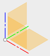
- Click the bulb icon once more to turn off the origin visibility.
- Position the mouse cursor over the Units heading in the browser. A Change Active Units icon (
 ) appears at the right end of the heading. Click this icon, and a CHANGE ACTIVE UNITS dialog box appears.
 - Click in the Unit Type field and select Inch from the drop-down menu.
- Click OK.
Tip: Alternatively, we could have changed the default modeling units in the Preferences dialog box prior to creating the new model. Changing units in the browser is convenient when you want to deviate from your usual unit system. - Create and name three components within the model assembly, as follows:
- Right-click the (Unsaved) heading at the top of the browser and select New Component from the context menu.
- Repeat this step two times to create a total of three Component subheadings.
- Click to select the Component1:1 heading. Then, click once more to edit the name. Type Board and press Enter.
- In the same manner, rename the second component to Chip.
- Rename the third component to Edge Connector.
- Right-click the (Unsaved) heading at the top of the browser and select New Component from the context menu.
- In the QAT, click
 Save the document.
 - Navigate to the folder where you want your CAD model, and subsequent Simulation Mechanical tutorial model, to be located. Type Circuit Board in the File name field.
- Click Save. Notice that the model name now appears at the top of the browser, where it previously said (Unsaved).