The interoperability between Autodesk® CFD and Autodesk® Simulation Mechanical supports fluid structural interaction (FSI). Specifically, this implementation is a type of one-way coupled multiphysics analysis. You apply the fluid boundary reactions (that is, static pressure results) from a CFD simulation as loads on a structural analysis model. The software converts the CFD static pressures (at the fluid-to-solid part boundaries) to nodal forces on the Mechanical model.
The meshes do not have to be identical, but you must base both meshes on the same CAD geometry. The interoperation process verifies that the CFD and Mechanical models have matching CAD geometry. The meshing requirements for CFD and structural analyses can be considerably different. Mapping the pressure on the element faces of one mesh to forces on the nodes of a dissimilar mesh provides significant modeling flexibility. This process allows you to use the most appropriate type of mesh for each respective analysis type.
The following Simulation Mechanical analysis types support FSI workflows using Autodesk CFD results:
-
Linear:
- Static Stress with Linear Material Models 1
- Natural Frequency (Modal) with Load Stiffening
- Critical Buckling Load
-
Nonlinear:
2
- MES with Nonlinear Material Models
- Static Stress with Nonlinear Material Models
- A Fluid Reaction column is included within the Load Case Multipliers table in the Analysis Parameters dialog box for linear static stress analyses. You can apply reaction forces from an Autodesk CFD analysis as a load in multiple load cases, and with varying multiplication factors.
- If running a nonlinear analysis in Simulation Mechanical, you must use Load Curve 1 to control the magnitude of the fluid reaction forces as a function of time. Use Load Curve 2 and above to control any other applied loads.
The Autodesk CFD fluid flow analysis can be either steady-state or transient. However, if the CFD analysis is transient, you must choose a single time step from which to apply the results to the Simulation Mechanical model.
Currently, fluid structural interaction between CFD and Mechanical is limited to 3D models based on CAD solid geometry.
Example
Here is an example of one-way FSI. Determine whether a product, in this case an outdoor lamp post, can withstand the wind loads experienced during severe weather conditions. In the CAD model, include a fluid region that encompasses the above-ground portion of the lamp post.
Import the CAD model into Autodesk CFD. Define the fluid as Air. Specify a fluid velocity of 150 miles per hour (our wind speed) at the fluid inlet surface. Complete the necessary meshing and setup of a stead-state fluid flow analysis, and run the simulation.
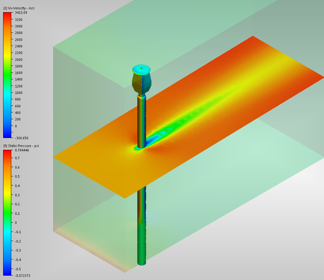
Figure 1: Static Pressure Results of CFD Analysis
Import the same CAD geometry into Simulation Mechanical, but suppress the part that represents the air. Constrain the bottom of the post (buried portion). Specify the source of fluid reaction forces; the CFD study and design scenario. Complete the necessary meshing and setup of a linear static stress analysis, and run the simulation.
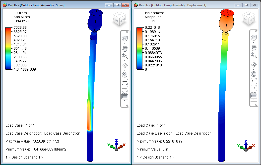
Figure 2: Von Mises Stress and Displacement Magnitude Results of Mechanical analysis.
Process
- Set up and run the fluid flow simulation in Autodesk CFD. Both fluid and solid parts are active for this phase.
- The two simulation programs do not both have to be installed on the same computer for interoperability to work. If Autodesk CFD and Mechanical are on different workstations, transfer the CFD model files to the Mechanical workstation. To facilitate transferring the necessary files, archive the study with results. Then, copy the *.cfz file to the Mechanical analysis computer, and extract the contents. The *.cfz file is a standard zip archive, which you can associate with your preferred zip file manager. Important: If you are running CFD and Mechanical on the same workstation, exit Autodesk CFD before proceeding further. Exiting Autodesk CFD closes the study and releases all of the results files so that Simulation Mechanical can properly access them.
- Import the same CAD model into Simulation Mechanical. Suppress the fluid part, which is not used in the structural analysis. Only the solid parts are considered.
- Access the Fluid Reactions tab of the Analysis Parameters dialog box. There are several ways to access this tab:
- Click Setup
 Loads CFD Results Fluid Reactions.
 - Click Setup Model SetupParameters to access the Analysis Parameters dialog box. Then, click the Fluid Reactions tab.
- Right-click the Analysis Type heading in the browser and choose the Edit Analysis Parameters command. Then, click the Fluid Reactions tab.
- Click Setup
- Choose Autodesk CFD file from the Source of Reaction Loads pull-down menu.
- Click Browse and navigate to the folder where the CFD study resides. Select the appropriate *.cfdst file and click Open.
- Select which design scenario to use from the CFD model using the pull-down menu immediately below the design study path and filename.
- You must specify which step to use for the reactions if either of the following two conditions apply. Use the Which step to use drop-down menu to select the step. This option does not appear in the dialog box if only one step is available for input.
- The selected design scenario is a transient fluid flow analysis from which multiple steps were output
- The selected design scenario is a steady-state analysis for which you chose to save intermediate steps.
- Click on the General tab of the Analysis Parameters dialog box and specify the desired multipliers in the Fluid Reaction column for each load case.
- Complete all required meshing and model setup steps. (Add constraints, apply other loads, define material properties, other load case multipliers, and so on.)
- Run the simulation.
- In addition to viewing stress, strain, and displacement results, you can verify the applied fluid reaction loads. Click Results Contours Other Results Reactions Applied Force, and choose one of the available options:
- Magnitude
- X
- Y
- Z
- Vector Plot
Note: The load mapping and interpolation process introduces a small amount of error between the CFD wall forces and the Mechanical reaction forces. This error is due to the differing size, shape, and orientation of the element faces between the CFD and Mechanical meshes. The comparative fluid boundary force results are typically within 10 or 15% of each other.Tip: You will tend to achieve better results when the Mechanical mesh is finer than the CFD mesh