In many models, it is necessary to simulate joints and pinned connections for rotational purposes. Modeling the actual joint components with surface to surface contact can result in long run times. Nonlinear iterations are required to determine where contact occurs between the mating surfaces. Additionally maintaining static stability of the model is more difficult in contact solutions.
In many cases, the effects at the actual joint components are not important, but the connectivity of the parts is. The easiest way to simulate a joint or pin while avoiding a long runtime is to create sets of Truss elements that connect the parts. Truss elements cannot resist rotation. They behave as if each endpoint is a ball joint. Therefore, they can position two parts relative to each other while allowing relative rotation.
Manually adding the required line elements to an existing meshed model can be tedious. When working with CAD models, the Joint command provides a quick and easy alternative to the manual process. Using this command, you can select the surfaces where you want to create a joint and automatically generate the required line elements.
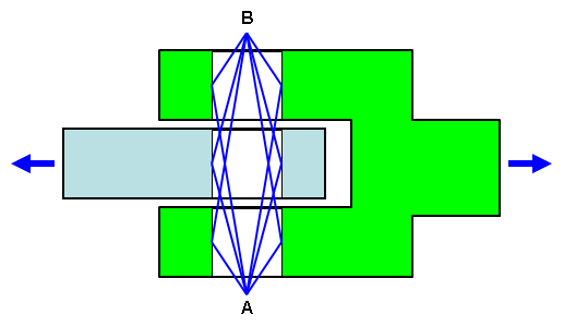
Figure 1: Schematic of a Pin Joint
Instead of modeling a true pin, a clevis and eye are connected with truss elements that simulate a pin joint. Truss elements from two points (A and B) are connected to each node on the selected surfaces. (To simplify this figure, only one line is shown from each point to each surface. Also, points A and B are moved outside the parts for clarity.)
A pin joint can be visualized as several separate sets of trusses. The truss elements (blue lines) that extend from the surfaces of the clevis (green body) to point A form one truss set. If the truss elements are sufficiently stiff, point A cannot move relative to the surface of the clevis. A second truss set is formed from the clevis to point B. Likewise, truss sets are created from the eye (light blue body) to points A and B. Because the ends of truss elements behave like ball-joint connections, the trusses and bodies they connect can rotate about the line A-B. However, they cannot translate relative to each other. Thus, a pin joint connection is simulated.
To Create a Joint
- Select all of the surfaces that you want to be involved with the joint. You can either select the surfaces in the model display area or from the Surfaces list under any part in the browser (tree view). In either case, be sure to hold down the <Ctrl> or <Shift> key to select multiple surfaces.
- Click
 Mesh
Mesh  CAD Additions Joint. The Joint Mesh Setup dialog box appears. The surfaces that you selected before clicking the Joint command are listed in the Participating surfaces section.
 - Alternatively, you can add or remove participating surfaces after accessing the Joint Mesh Setup dialog box. Select model surfaces and click Add to add surfaces to the Participating surfaces list. Conversely, select one or more items within the Participating surfaces list and click Remove to exclude them from participating.
- Choose the type of joint that you want to create in the Joint drop-down box selector.
- Pin joint (lines to axis endpoints): This option creates a classic pin joint, which rotates freely about a single axis direction. Two nodes are added (the axis endpoints). Every node along every participating surface is connected to both endpoints with line elements. Figure 1 represents this type of joint. The endpoint locations can be automatically determined, manually specified using coordinates, or manually selected from model vertices or construction vertices.
- Universal joint (lines to axis midpoint): This option creates a classic universal joint. The nodes along the participating surfaces are connected to a single midpoint node. See Figure 2. The midpoint location can be automatically determined, manually specified using coordinates, or manually selected from a model vertex or construction vertex.
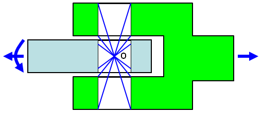
Figure 2: Schematic of a Universal Joint
Compare the universal joint to the pin joint. Instead of trusses being connected to two axis endpoints (A and B in Figure 1), they are connected to a single midpoint (O in Figure 2). Because the ends of truss elements behave like ball joint connections, the trusses and bodies they connect can rotate in any direction about point O. However, they cannot translate relative to each other. Thus, a universal or ball-and-socket type joint is simulated.
- The joint creator can usually decide where to locate the axis of rotation or center point based on the geometry of the participating surfaces. The default joint option, Automatic detection of axis/center-point, causes the endpoints of pin joints and the center point of universal joints to be located automatically. In some cases, the joint creator may have difficulty determining appropriate axis endpoint locations (for example, if the holes are curved, skewed, or tapered). A warning message indicates when automatic point detection is problematic. You may also want to manually specify the points to locate them outside of the width of the parts (as in Figure 1). To manually specify the axis of rotation or center point, activate the Manual axis/center-point specification radio button. Then, define the point or points using one of the following methods:
- Type the X, Y, and Z coordinates in the provided input fields.
- Click Point Selector and then select a vertex or construction vertex within the model display area.
When creating a pin joint, specify the locations of both endpoints of the rotation axis. When creating a universal joint, specify a single center point.
- Optionally, change the Part, Surface, or Layer number of the line elements using the provided input fields. For example, you can create multiple joints on the same part number if common cross section and material properties are suitable for all of them. By default, the next available (unused) part number is automatically assigned to each joint. However, it is not mandatory for joints to be unique parts.
- If you want to continue creating addition joints after this one, activate the Do not dismiss dialog after joint generation option. Once the current joint is created (next step), the Part field will be automatically incremented to the next available unused part number. Additionally, the Participating surfaces list will be cleared.
- Press OK to create the joint. If the mesh exists, the lines for the joint are created immediately. Otherwise, the lines are automatically created after you generate the 3D mesh (Mesh Mesh Generate 3D Mesh).
- To create another joint, repeat the process. If you activated the option, Do not dismiss dialog after joint generation (step 6):
- Select the participating surfaces for the next joint.
- Click Add.
- Continue repeating the joint setup process from step 3.
- To edit the specifications of a joint, select the appropriate Joint Mesh heading in the Meshes branch of the browser, right-click, and choose Edit.
- To delete a previously created joint, select it in the browser, right-click, and choose Delete.
- To rename a Joint Mesh item, select it in the browser, right-click, and choose Rename.
- To create another joint, repeat the process. If you activated the option, Do not dismiss dialog after joint generation (step 6):
- Define the cross-sectional area of the truss elements in the Element Definition dialog box, and define the material for the truss element part.
- Alternatively, if the joint needs to transmit a moment (rotational load or constraint), change the element type from Truss to Beam. Then, define the beam cross section and material properties.
Potential Pin Joint Issue
Assume that two parts are in contact (no gap between them), and the contact type is free or surface contact. In addition, assume that a pin joint is used to connect the two parts. Where two parts meet (such as at the contact surface edges), line elements are connected to nodes belonging to one part, not both parts. This connection methodology prevents the parts from becoming locked together. Locking occurs if coincident nodes from two parts are connected to the same truss element. The joint must be free to articulate.
Considering the creation method used for pin joints, this situation is usually not a problem. However, if a joint behaves as if it is locked, then change the CAD model to provide a gap between the adjacent parts. Alternatively, use one of the following methods:
- Make the hole diameters different for the mating parts. This method prevents the possibility of coincident nodes at the edges of joint surfaces because the edges are not coincident.
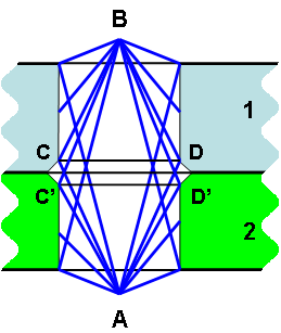
- Add a chamfer around one or more contact edges (as shown in the below-right figure). To ensure that the joint is free to articulate, do not include the chamfers as participating surfaces of the joint.
|
|
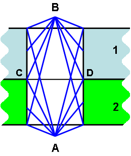
| Parts 1 (light blue body) and 2 (green body) are in surface contact. Two sets of nodes exist along the line C-D. However, the pin joint elements (blue lines) are generally connected to only one set of nodes along C-D, not to both set of nodes. So, the joint is normally free to articulate. If, for some reason, the joint behaves as if it is locked, use the modified geometry shown on the right to correct the problem. | When you place a chamfer on one or both parts, the two cylindrical surfaces, to which the pin joint is applied, have no coincident edges. One set of truss elements is connected to the nodes along C-D, and another set of truss elements is connected to nodes along C'-D'. The possibility of any truss being connected to coincident nodes of the two parts is eliminated, ensuring that the joint is free to articulate. |