The general contact element has three basic states which results in an element with four distinct regions of stiffness:
- Contact (locked): Element stiffens for lengths below a specified value (compression).
- Coupling: Element stiffens for lengths above a specified value (tension).
- Unlocked State: Element stiffness depends on whether the element is in tension or compression.
Material damping parameters can have distinct values depending on whether the element is locked, coupled, or unlocked.
General Contact Element Parameters
The first parameters that must be specified for a general contact element part are in the General tab of the Element Definition dialog. You must input the area of the constant cross-section in the Cross-Sectional Area field. You must specify the mass of the general contact element based on the initial length. The same value remains in effect regardless of the length to which the element is stretched or compressed during the course of the analysis. If gravity or acceleration loads are going to be present in the model, you must specify a value in either the Element Mass field or the Mass Density field.
For the general contact elements to have a stiffness applied when they are not in a coupled or contact state, specify the moduli in tension and compression in the Unlocked Tension Modulus and Unlocked Compression Modulus fields in the Unlocked tab. If you specify a value in the Resistant Force field, it will be applied as an axial force.
For the general contact elements to have a stiffness applied when the length becomes shorter than a certain value, specify the length in the Contact Distance field in the Contact tab and specify the modulus in the Contact Modulus field. Since the element cannot become shorter than 0 units, a contact distance of 0 is not a realistic distance for true contact. Use a small, finite value for the contact distance. Use a value of 0 if you do not want any contact region.
For the general contact elements to have a stiffness applied when the length becomes longer than a certain value, specify the length in the Coupling Length field in the Coupling tab and specify the modulus in the Coupling Modulus field. A value of 0 indicates there is no coupling region.
In all cases (unlocked, contact, and coupling), the stiffness of the element will be the product of the modulus (E) and cross-sectional area (A) divided by the length (L), or stiffness = A*E/L. The length L depends on the length of the element as drawn in the model and the input lengths of contact distance and coupling length. Refer to the following figure and table.
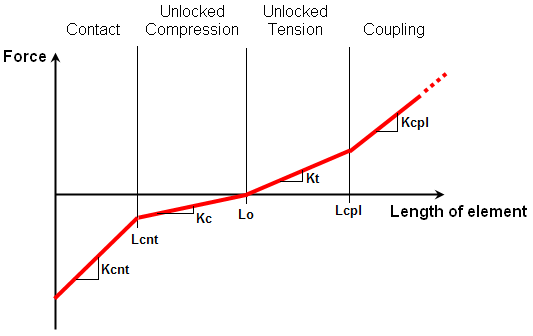
Figure 1: Stiffness of General Contact Element
where
- Lcnt is Contact Distance
- Lo is the length of the element as drawn in the model. Note that each element with a different length will have a different stiffness.
- Lcpl is Coupling Length
- Kcnt is the stiffness of the element when in the Contact region. The length is less than Lcnt.
- Kc is the stiffness of the element when in the Unlocked Compression region. The length is between Lo and Lcnt.
- Kt is the stiffness of the element when in the Unlocked Tension region. The length is between Lo and Lcpl.
- Kcpl is the stiffness of the element when in the Coupling region. The length is greater than Lcpl.
| Initial Element Length, Lo | |||
|---|---|---|---|
| Lo < Lcnt | Lcnt < Lo < Lcpl | Lo > Lcpl | |
| Stiffness, K |
Kcnt = A*Ec/Lcnt + A*Ecnt/Lcnt no unlocked compression Kt = A*Et/Lcnt Kcpl = Kt + A*Ecpl/Lcpl |
Kcnt = Kc + A*Ecnt/Lcnt Kc = A*Ec/Lo Kt = A*Et/Lo Kcpl = Kt + A*Ecpl/Lcpl |
Kcnt = Kc + A*Ecnt/Lcnt Kc = A*Ec/Lo no unlocked tension Kcpl (for L>Lo) = A*Et/Lo + A*Ecpl/Lcpl Kcpl (for L<Lo) = A*Ec/Lo + A*Ecpl/Lcpl |
| Initial Force, Fo | Fo = 0 | Fo = 0 | Fo = Kcpl*(Lo-Lcpl) |
| where Ecnt, Ec, Et, and Ecpl are moduli for contact, unlocked compression, unlocked tension, and coupling, respectively. | |||
For a damping force to be applied to the general contact element, enter a value in the Dashpot Coefficient field in the Damping tab. The damping force will be proportional to this value and the cross-sectional area. For the damping effects of the material to be accounted for, specify the damping coefficient for each state in the Unlocked Damping, Locked Damping, and Coupling Damping fields. In order for these properties to affect the calculated forces and stresses, activate the Output includes damping effects check box.
You can specify tensile and compressive stress limits for general contact elements. Once either of these stresses is surpassed the element will break. You can specify these stresses in the appropriate Breaking Stress fields in the Breaking tab. In order for this field to be available, you must select an option other than None in the Breaking disables drop-down box. If the Unlocked condition option is selected, the unlocked modulus will be set to 0 after the tensile or compressive stress exceeds the breaking stress. If the Coupling condition option is selected, the coupling modulus will be set to 0 after the tensile stress exceeds the breaking stress. If the Contact condition option is selected, the contact modulus will be set to 0 after the compressive stress exceeds the breaking stress. If the Both unlocked and coupling condition option is selected, the unlocked and coupling moduli will be set to 0 after the tensile stress exceeds the breaking stress. If the Both unlocked and contact condition option is selected, the unlocked and contact moduli will be set to 0 after the compressive stress exceeds the breaking stress.
Basic Steps for Use of General Contact Elements
- Be sure that a unit system is defined.
- Be sure that the model is using a nonlinear analysis type.
- Right-click the Element Type heading for the part that you want to be general contact elements
- Select the General Contact command.
- Right-click the Element Definition heading.
- Select the Edit Element Definition command.
- In the General tab, enter the cross-sectional area of the elements in the Cross-Sectional Area field. This is required information and the model will not run without it being entered.
- Optionally, specify a value in the Element Mass field. This value will be used for the element regardless if it is stretched or compressed.
- If you are going to apply gravity to your model, specify a Mass Density for the elements.
- Click the Unlocked tab. Specify the appropriate values for the unlocked state.
- Click the Contact tab. Specify the appropriate values for the locked state.
- Click the Coupling tab. Specify the appropriate values for the coupled state.
- Click the Damping tab. Specify the appropriate damping values.
- Press the OK button.