The commands on this page are accessed from the Draw and Design panels on the Draw tab.
Common Items
When geometries --- such as lines, arcs, circles --- are added to a model, the objects can be of two different types:
- Use as Construction When this box is activated, the added geometry object is not part of the mesh. Instead, it is used as an aid to build a mesh (either an automatic 2D meshed region, or structured mesh, both described later). For example, four construction lines connected together to form a rectangle do not create a plate element when the analysis is performed. Construction arcs, circles, and splines are shown as their theoretical smooth objects. Construction objects are listed in the tree view either under the drawing plane/sketch branch or under the <3D Objects> branch, from which the objects can be modified (change the coordinates of the defining points, change the attributes, and so on). (See the Drawing Planes page for the distinction between a drawing plane/sketch and a 3D object, and for methods to move an item from 3D space to a sketch.)
- Regular Lines: When the added object is not a construction object, it will be used as part of the mesh. For example, four lines connected together to form a rectangle do create a plate element when the analysis is performed. Since the objects are part of the mesh, non-construction arcs, circles, and splines are immediately divided into straight line segments when they are added to the model. That is, the arcs and circles are meshed.
See the Modify Attributes and Duplicate page for instructions on changing an item from a construction object to a regular line and vice versa.
When adding geometry, the points can be entered with any of these methods:
- Enter the X, Y, and Z coordinates of the point in the respective fields and press <Enter>. If the Use Relative check box is activated, the values entered in the DX, DY, and DZ fields will specify the relative distance in those directions from the current coordinate (shown in the status bar). For example, if the from point is (X=10, Y=5, Z=2.5) and you type ---1 in the DY: field and 2.5 in the DZ: field, a point will be defined at (X=10, Y=4, Z=5) instead of (X=0,Y=-1, Z=2.5).
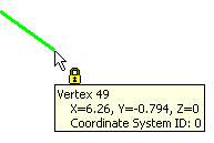
- Snap to an existing point. Move the cursor to the point where you want to begin; once the lock icon appears (see image below), left click the mouse to select that vertex.
- If using sketch mode, left click the mouse to snap to a grid point or at any free-hand position on the plane.
- Enter the vertex ID of the vertex in the model at which you want to begin the line in the ID: field. The vertex ID of a vertex can be determined by hovering the cursor over a point. A pop-up will appear with the vertex ID as shown below.
Add a New Part to a Model
New Part: Selecting this command adds an empty part with the next available part number. Any type of geometry can be added to this part.
Add Construction Nodes to a Model
Construction Vertex: Use this command to add a vertex (node) to the model. Construction vertices have two purposes:
- Used as a reference point to add hand-built geometry to the model, such as lines, arcs, meshes, and so on. This vertex will not be included when the model is analyzed (unless of course an element is connected to the vertex).
- When working with a CAD solid model, construction vertices will force the surface mesher to create a node at that location. Refer to the Construction Vertices -Seed Points page for details.
- The Define Construction Vertex dialog will appear.
- Enter the coordinates where you want the construction vertex to be added.
- Press <Enter> to add the vertex.
 Visibility Construction Vertices to display or hide the construction vertices.
 Add Lines to a Model
Line: Use this command to add a line segments to the model. This segments can be defined as any line element.
- The Define Geometry dialog will appear.
- First specify the part, surface and layer to which the lines will be assigned in the Attributes section. The lines can be placed in any surface or layer number.
- Specify the beginning coordinate for the line using one of the above methods in Common Items. If you move the mouse, you will see that the cursor is rubberbanded to the endpoint.
- Specify the second endpoint of the line. You will see the line appear in the viewing area.
- You can continue to add more lines in this dialog. You can either continue from the last endpoint, or can start a separate line. This can be controlled by the Single Line check box.
- To enter a series of line elements that are connected together to form a continuous chain, make sure that the Single Line check box is deactivated.
- To define separate lines that do not connect together, make sure that the Single Line check box is activated.
Modify Set Search Tolerance dialog. This rule has an effect when adding geometry, copying, meshing, and so on.  Options Sketching tab.
 Generate Tangent Lines
Selecting the Tangent Line command guides you through the process of creating tangent lines between construction circles and arcs. This command will only be available if an arc or circle exists in the current sketch. Following the prompts in the status bar, the tangent lines are created as follows:
- Click the first object for the tangent: either a construction vertex, circle, or arc.
- Click the second object for the tangent: either a construction circle or arc (or vertex if the first object was not a construction vertex). All possible tangent lines between the two objects will be shown.
- Select each possible tangent line that you want in the model. Use the <Ctrl>, <Shift> and <Ctrl>+<Shift> to toggle, add, and subtract lines to the selection set.
- Press the <Enter> key after selecting the desired lines. Construction lines will be created at the selected tangent lines.
Add Rectangles to a Model
Rectangle: Use this command to add four line segments that define a rectangle.
- The Add Rectangle dialog box appears.
- First specify the part, surface and layer to which the lines generated from the rectangle will be assigned in the Attributes section.
- If not in sketch mode, then four points will be required to define the rectangle. If in sketch mode, only the two diagonally opposite points are required. Each of these points can be entered as described above in Common Items. The four points are as follows:
- The first point defined must be a corner of the rectangle.
- The second point defined must be the corner of the rectangle opposite to the first point.
- The third point defined can be any point that lies in the plane of the rectangle. This point cannot lie along the diagonal defined by the first two points.
- The fourth point defined can be any point on the base of the rectangle.
- Press the Apply button to create the line segments.
- For example, to create a 10 x 10 rectangle at the origin in the XY plane at Z=0 and sides parallel to X and Y, you would use the following coordinates for the four points:
- (0,0,0) for the first corner
- (10,10,0) for the opposite corner
- (2,3,0) or any coordinate where the X and Y values are unequal (so that they are not on the diagonal) and Z=0.
- (1,0,0) or any coordinate along the X axis, except for (0,0,0).
Add Arcs to a Model
Arcs can be added in 3D space using Arc Three Points or Arc Center and Endpoints. When in sketch mode, arcs can also be entered by specifying the Angle and Endpoints or Radius and Endpoints.
- The Define Arc using dialog will appear.
- First specify the part, surface and layer to which the arc (or lines) will be assigned in the Attributes section.
- If not creating a construction object, specify how many line segments into which the arc will be divided in the Minimum Segments: field. The segments will be of equal length. To control the lengths of the lines create from the arc, activate the Maximum Length: check box and specify the maximum length of the line segments that will be generated in the adjacent field. If the length of the arc divided by the value in the Minimum Segments: field is greater than this value, more segments will be generated than specified in the Minimum Segments: field.
- Define the points for the arc, following the prompts in the status bar. Each of these points can be entered as described above in Common Items.
- For some arc commands that have a direction, activate the Reverse Sense of Arc check box to have the other section of the arc displayed.
- Press the Apply button to create the arc or line segments.
Add Circles to a Model
Circle Diameter or Circle Center and Radius: Use these commands to add circles to the model.
- The Define a Circle by Diameter Points or Define a Circle by Center and Radial Point dialog will appear.
- First specify the part, surface and layer to which the lines generated from the circle will be assigned in the Attributes section.
- If not creating a construction object, specify how many line segments into which the circle will be divided in the Minimum Segments: field. The segments will be of equal length. To control the lengths of the lines create from the circle, activate the Maximum Length: check box and specify the maximum length of the line segments that will be generated in the adjacent field. If the circumference of the circle divided by the value in the Minimum Segments: field is greater than this value, more segments will be generated than specified in the Minimum Segments: field.
- Define the points for the circle, following the prompts in the status bar. Each of these points can be entered as described above in Common Items.
- Press the Apply button to create the line segments.
Add Splines to a Model
Spline Curve: Use this command to add splines to the model.
- The Add Spline dialog will appear.
- First specify the part, surface and layer to which the lines generated from the spline will be assigned in the Attributes section.
- If not creating a construction object, specify how many line segments into which the spline will be divided in the Minimum Segments: field. The segments will be of equal length. To control the lengths of the lines create from the spline, activate the Maximum Length: check box and specify the maximum length of the line segments that will be generated in the adjacent field. If the length of the spline divided by the value in the Minimum Segments: field is greater than this value, more segments will be generated than specified in the Minimum Segments: field.
- Specify the degree of curvature that will be used to generate the spline in the Degree: field.
- If you want the spline to pass through all of the defined points, activate the Interpolate check box.
- If you want the first and last point to be connected, activate the Close check box.
- Define the points that will be used to generate the spline. Each of these points can be entered as described above in Common Items.
- Press the Apply button to create the spline or line segments.
Add a Pulley Element
Pulley: This command is available only in a nonlinear analysis. See Pulley Elements for more details.
Add Contact Elements to a Model
Contact Elements: This command will add numerous lines between two sets of vertices on the model. The main use for this command is to create contact or gap elements between every node in one area and every node in another area. But since the command simply creates lines, the lines can be used for any purpose and any element type.
The steps for using the command are as follows:
- After this command is started, select one of the two sets of vertices in the display area, such as one of the faces for contact. You can use any selection method to select any type of object. For example, if you select an entire part or surface, all of the vertices on that part or surface will be included. If you select a line, both vertices will be selected. Construction vertices can also be selected, but other construction objects cannot be selected.
- Press the Assign Set 1 button. The number of vertices selected will be listed.
- Select the second set of vertices to connect, such as the second contact face.
- Press the Assign Set 2 button. The number of vertices selected will be listed.
- Specify the attributes of the lines in the Part, Surface, and Layer fields.
- Press the Create Lines button to create the contact elements. Every vertex in the first set will be connected with a line to every other vertex in the second set.
In some situations, you may only want contact elements to be created between nodes that are a certain distance apart. For example, if you know that a part is only going to move 1 inch relative to another part, you do not need contact elements longer than 1.5 inches (leaving a little leeway). This can be done by activating the Constrain lengths check box and specifying the minimum and maximum lengths. Then, only lines whose length is within the constraints will be created when the Create Lines button is pressed.
Layer Control
Layer Control: Displays lines according to the layer attribute (layer number) and filters the lines for easier selection. The dialog box shows all the layer numbers in the model, regardless of part. Select Show to display all the layers in the model. You can also select to show individual layers. For selection, activate Filter to prevent the object from being selected. Filtering works on any type of object: part, surface, edge, line, and vertex. If the object belongs only to lines on a layer that is filtered, then the object is not selected.
Centroid Creator: Connect Lines to the Centroid of Surfaces or Edges
The general purpose of this command is to calculate the centroid location of a set of surfaces or edges, and to place a construction vertex at this centroid. Optionally, you can connect the nodes on the selected surfaces or edges to the centroid with line elements. Thirdly, you can specify a secondary set of surfaces or edges and connect the two centroids together with a line element. So, there are three levels of Centroid Creator functionality:
- Specify only the Primary Centroid Geometry with no other options activated: A single construction vertex is created at the centroid of the specified surfaces or edges.
- Specify the Primary Centroid Geometry and activate the Connect centroid to geometry with "spokes" option: Every node on the specified surfaces or edges is connected to a construction vertex at the centroid of the specified surfaces or edges.
- Activate the Connect primary centroid to secondary centroid option and specify the Secondary Centroid Geometry too: Construction vertices are placed at the centroids of both sets of centroid geometry—primary and secondary. In addition, line elements are added to connect each node on the specified surfaces or edges to their respective centroids. Finally, the two centroids are connected together with a single line element. Note: Activating option 2 is a prerequisite to activating option 3. You cannot specify the Secondary Centroid Geometry or connect the two centroids together unless you first choose to connect the centroid to the geometry with spokes.
For example, consider a long channel used in a structure, and the interaction of the bolted connections at each end are to be studied in detail. So a CAD model of the beam, bolts, and connection is created. If the span of the channel is not of interest in the analysis, it can be replaced with a few beam elements to greatly reduce the size of the analysis. The Centroid Calculator automates the process of connecting each node on the cut end of the channel to the centroid, and then connecting the two centroids. See the following figure.
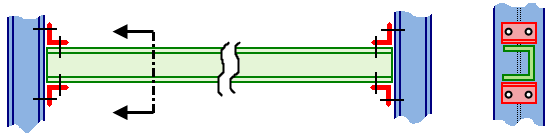
(a) Full CAD model in which the entire horizontal channel is modeled with brick elements.
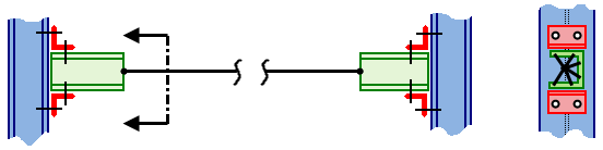
(b) More efficient model in which a portion of the horizontal channel is modeled with beam elements. Only the end connection portion, requiring the detail provided by brick elements, is represented in the CAD model.
The steps for using the Centroid Creator command are as follows:
- Although not mandatory, the recommended workflow is to mesh the model prior to using the Centroid Creator whenever you will be adding spokes. In this way, the spokes are generated immediately upon completing the command.
- Select the surfaces or edges to for which you want to create a centroid (Selection Select Surfaces or Selection Select Edges).
- Activate the Draw DesignCentroid Creator command. Selected surfaces or edges are listed in the Primary Centroid Geometry box.
- Additional surfaces or edges can be selected in the display area and added to the list in the box by clicking Add. You cannot mix surfaces and edges within a centroid geometry box. The list can consist of one or more surfaces, or one or more edges, but not a mixture of both types of entities. Undesired entities can be removed by selecting them in the box and clicking Remove.
- If you want each node on the specified surface or edge set to be connected to the centroid, activate the Connect centroid to surface with spokes option. In the Part number input field, indicate which part number to use for the lines. Note that the spokes will not be generated unless the model has been meshed prior to using the Centroid Creator command. Otherwise, spoke generation is deferred until the model is subsequently meshed.
- To connect a secondary surface or edge set (using line elements) to its centroid and also to the primary centroid, activate the Connect primary centroid to secondary centroid option. Then, select the surfaces or edges for the Secondary Centroid Geometry and click the secondary Add button.
- Click OK to perform the operations.
- A Centroid Mesh item is added to the browser and appears under the Meshes heading. You can right-click the Centroid Mesh x heading and either Edit or Delete the associated centroid mesh. You do not have to delete and recreate centroid meshes to change the geometry sets or connection options.
- The Centroid Creator only works on surfaces or edges of CAD-based models. The calculation of the centroid is not dependent on the mesh size.
- For all options chosen in the dialog box, a construction vertex is placed at the centroid of the specified surfaces or edges. If the model is re-meshed, and if one of the construction vertices is near the surface of the model, a node will be created at the centroid location by the meshing process. See the Construction Vertices -Seed Points page for details. This behavior bonds the line elements at the centroid to the surface of the CAD-based part. If this connection, or the slight distortion of the surface mesh, is not desired, select the construction vertex (Selection Select Construction Objects) and delete it before re-meshing.
- The centroid spokes are associative with the model, so if the model is re-meshed, the spokes are recreated in the appropriate number and location.
- Provide multiple calculation points (nodes) along the length of the connecting/spanning member when it is a beam element. Select the line (Selection Select Lines) and divide it into multiple shorter increments (Draw Modify Divide). Do not divide this line if you are specifying truss elements for the centroid creator geometry.
- Right-click the part heading of the centroid creator part in the browser and choose Isolate. All other parts are hidden, allowing you to easily select only lines belonging to the centroid creator geometry.
- Click and drag the mouse making a selection window around the spokes at one centroid. ( Use the Selection Select Lines selection mode.) Note: It is important that you select only one of the two sets of spokes. You will be converting these lines to a rigid element part. Rigid elements must consist of only one master node per part and any number of slave nodes. The centroid node is the master, because it is common to every spoke. The outer ends of the spokes are the slave nodes, which move exactly as the master node does (rigid connection from master to slaves).
- Click Draw Modify Attributes. Then,
- Specify an unused part number in the Part field.
- Click OK. A new part appears in the Parts list of the browser.
- Repeat steps 2 and 3 for the opposite set of spokes.
- Change the element type for both of the new parts to Rigid.
- Open the Element Definition dialog box for both rigid parts and click OK to accept the default parameters.
- Right-click the Parts heading in the browser and choose Show All Surfaces to restore the visibility of all of the parts.