This appendix gives some examples of using the Nodal Results Translator. The examples on this page are.
Adjust Results by a Fixed Amount: Your heat transfer analysis has just taken a long time to complete, and you have just discovered that a typing mistake has resulted in all the temperatures being 200 degrees too hot. The client is coming to your office in 5 minutes. What are you going to do?
- Make a copy of the temperature results file (either .TO or .TTO). You should keep this copy since they are the analytical results based on the input.
- Run the Nodal Results Translator. On the Input File and Options tab, specify the copy as the Existing Results File.
- The Load Case and Node Output tab should be set to output all load cases.
- On the Output File and Options tab, specify the original model name as the New Results File and overwrite it. (The Results environment will read this file to display the adjusted results.)
- Specify -200 (negative 200) for the Temperature Adjustment Value. This will reduce all calculated temperatures by 200 degrees. (For a heat transfer analysis, only the second degree of freedom, the temperature, is used.)
- Click the Create File button. The .TO or .TTO file will contain the adjusted results. You can now review the results as you would normally.
Output Result of Last Time Step: Imagine a Mechanical Event Simulation (MES) in which the applied force is a function of the vertical (Z) displacement of nodes 61 and 70. Since loads in MES are a function of time, not of any result, you write a program that will update the load curve for the applied force based on the previous deflection. In your application, you run TranDO_i automatically to get the output from the last step. The other tasks needed to complete the project are controlled by your application. (Tasks include: averaging the results output by TranDO_i, changing the load curve in the model's database, resuming the MES analysis for 1 time step, repeating the process after each time step.) To run TranDO_i automatically, you create a Recall Input file as follows:
- Run your MES analysis manually for the first time step.
- Run the Nodal Results Translator from the Results environment. On the Input File and Options tab, specify your analysis as the Existing Results File.
- On the Load Case and Node Output tab, choose Specify Load Cases and Nodes. In Row 1, enter a Time Step of 30000. You will get a warning message that this time step is beyond the range of the current results 0-1. Click OK. When the New Results file is created, this invalid time step will automatically be adjusted to the last time step in the analysis, as shown in the error log file.
- In Row 1, enter the Node(s) to output as 61, 70.
- On the Output File and Options tab, specify a text format for the New Results file. Specify the filename and any Text Output Options.
- Since only the Z displacement is required, turn off all the check marks except for the Displ. z in the Adjustment Values section.
- Click the Store Input button to save the input to a file.
When TranDO_i is executed from your application, there should be only one warning error in the error log file (TranDO2.log). It is the same error that occurred when you were setting up the Recall Input file.
Nodal Results Translator 16.000
'documentation example.lcn' read at 01-05-2003 12:00:23
Error # 5: Time step 30000 out of range of 0- 1
Number of fatal errors..: 0
Number of warning errors: 1
Since this is just a warning (known ahead of time) and not an error, the output file is created properly. Your application can proceed with its work.
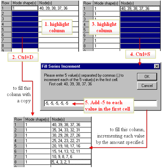
Reverse the Results: Imagine that for whatever reason, you want to have the results for a 40 node model output in reverse order, from the last node to the first node. The Load case spreadsheet is the obvious way to accomplish this. Unfortunately, the nodes cannot be specified as 40-1; the Nodal Results Translator automatically reverses the node order to be in ascending order (nodes 1-40) when the Create File button is clicked. Instead, enter the first row of data, and then use the hot keys to fill in the load case spreadsheet using the 5 steps shown in the figure. To make the grid easier to read (and easier to type), enter the first 5 node numbers on the first row, in reverse order of course.
List of Node Numbers: To use the load case spreadsheet to specify a series of nodes to output but dread the thought of writing down all those numbers, then consider doing the following:
- Run the Nodal Results Translator and specify all the input as normal. Specify at least one row in the load case spreadsheet, or specify the load cases but leave the node cell(s) empty.
- Click the Save Input button to save the input to an .LCN file.
- Edit the .LCN file using a text editor.
- To get the node numbers to fill in the .LCN file, open your model in the Results environment.
- Display the result of interest or a similar result. These results will not be used per se.
- Select the nodes for which you want the results output. If you want all the nodes on a part, click the part in the tree view and wait for the nodes to highlight.
- Inquire on the results. The selected nodes will be shown in the Inquire: Results window.
- Click the Save Values button. The results can be saved to a text file (.OUT) or comma-separated value file (.CSV). The .CSV format may be more convenient for the next step.
- Open the file just created. Copy the node numbers from this file and paste them into the .LCN file at the appropriate location. Whether the node numbers are on one line or many is not important. It's more a matter of personal preference. Remember that multiple nodes can be specified on each line of the .LCN file by separating them with a comma, and a range of nodes can be specified by using a dash.
- Save the .LCN file.
- In the Nodal Results Translator, click the Load Input button to load the settings. The load case spreadsheet will have the node numbers that you added to the LCN file.
Total Reaction Force: Imagine a static stress analysis with 20 load cases from which you want the total reaction force in the Z direction for each load case. The Nodal Results Translator can output the reaction at each of the supports. Then you can import the results into a spreadsheet and sum them. Here's how.
- Start the Nodal Results Translator and select the existing Linear Static Stress reaction forces (*.ro) file.
- On the Load Case and Node Output tab, select the load case spreadsheet (Specify Load Cases and Nodes).
- Insert rows until 20 rows are in the spreadsheet (for the 20 load cases to output).
- For the load case in row 1, enter a value of 3. (Recall from the Appendix Analysis Types and Codes in the DO File that reaction forces are grouped in sets of 3 load cases for linear static stress. Load case 3 is the support reactions for the first case. This is also indicated in the load case list.)
- Highlight the load case column and press Ctrl+S (or right-click and choose Fill Series). Enter an increment of 3 on the Fill Series Increment pop-up and click OK. This fills in all the load cases.
- Enter the node numbers for the supports in row 1. Highlight the Node(s) column and press Ctrl+D (or right-click and choose Copy Down).
- On the Output File and Options tab, indicate to output the results to a text file and specify a Comma Separated Variable (*.csv) file. This will make it easy to import into a spreadsheet.
- Check the box for Group results on single row.
- Uncheck all the Adjustment Value boxes except for the Force z box.
- Create the new results file and open it with your spreadsheet program.
- The case number and support reaction at the individual nodes are not of interest in this case. So insert two columns into the spreadsheet. In the first column, add a formula for the real load case which equals the file's load case divided by 3 (formula in cell A11 = C11/3, copied down the 20 rows). In the second column, add a formula that sums the values for all the nodes on the row (formula in cell B11 = sum(D11:J11) if there are 7 nodes with supports).
The Results environment can also perform this function by graphing the result at the selected nodes. Also, the summary file from the processor lists the total reaction force for the model for each load case.