When Should You Selectively Remesh Individual Parts?
There are situations where it might be advantageous to remesh individual parts of an assembly. For example, suppose that the majority of parts in a large assembly surface and solid mesh successfully, with adequate mesh quality. However:
- surface meshing fails for one or more parts,
- the mesh quality is poor for a limited number of parts, or
- solid meshing fails for one or more parts
In such cases, adjusting the mesh size of, or adding refinement to, individual parts can be more efficient than remeshing the entire assembly.
How to Selectively Remesh Parts
The same command that is used to mesh an entire model is also used to remesh individual parts. To prevent parts with acceptable meshes from being remeshed, Suppress them. While suppressed, parts are ignored by the mesh engine, and their prior meshes are retained. Follow this procedure:
- Select all of the parts that you do NOT want to remesh. Either select the part headings in the browser, or use the Selection
 Select Parts mode and select the parts in the display area.
 - Right-click on a selected part heading or in the display area and activate the Suppress option. The parts remain visible until you press <Esc> or click in the background of the model display area.
- Adjust the meshing parameters for the remaining parts (the ones to be remeshed), or apply refinement to points, edges, or surfaces.
- Click Mesh Mesh Generate 3D Mesh.
- Repeat steps 3 and 4 if required to produce a satisfactory surface mesh on all active parts.
- Select the suppressed parts in the browser, right-click on a selected heading, and deactivate the Suppressed option. These parts will reappear in the display area.
- Click Setup Model Setup Parameters.
- Go to the Contact tab of the Analysis Parameters dialog box.
- Enable smart bonded/welded contact by choosing one of the following two options from the drop-down box in the Bonded Contact section:
- Coarse bonded to fine mesh
- Fine bonded to coarse mesh
Important: Smart bonding is necessary in most selective part remeshing situations. Normally, adjacent parts of an assembly have conformal meshes where they contact each other. That is, the lines and nodes of each part match along the contact surfaces. However, when a part is remeshed with the adjacent parts suppressed, the meshes will no longer be conformal. Smart bonding uses multipoint constraint equations (MPCs) to connect the adjacent part surfaces (for bonded contact) or edges (for welded contact). The meshes do not need to match each other.
Limitations
In some situations, you will not be able to selectively remesh parts of an assembly. In the cases that follow, you must remesh the whole assembly (or at least some additional parts) rather than just the parts with problematic meshes.
Surface Contact (Linear Static Stress) and Thermal Contact (Heat Transfer)
For linear static stress and heat transfer analyses, conformal meshes are required between parts that are in surface contact with each other. That is, the lines and nodal coordinates must match along the contact surfaces. Smart bonded contact only works when the contact type is Bonded or Welded. Therefore, the parts will no longer interact with each other after selective remeshing of only one of the contacting parts.
For any contact type other than bonded or welded, if any part is remeshed, the other part or parts that it contacts must also be remeshed. In turn, any other parts in contact with those parts must be remeshed as well.
Plate or Shell Elements with Only an Edge Contacting an Adjacent Part
Smart bonding is designed to work for contact along surfaces (that is, when the surface of one part is coplanar with the surface of another part). It is not designed to work when only an edge of one part intersects the surface of another (such as when surfaces intersect in a "T" or "L" configuration). Similarly, tied contact in nonlinear analyses does not work well for edge contact. Only translation is restricted. Rotational motion is not restricted. Therefore, connections can act like hinges.
Since the mesh between parts is no longer conformal (matched) after selective remeshing of parts, and neither smart bonding nor tied contact can maintain the proper connectivity, you have to remesh both parts if they intersect only along an edge. In turn, you may have to remesh additional adjacent parts as well.
Midplane Meshes
When two midplane-meshed parts intersect, the midplane surface of one part must be extended to intersect the midplane of the adjacent part. The figure below demonstrates the need for extended surfaces:
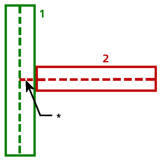
Figure 1: Extension of Midplane Surface Where Parts Intersect
The midplane of Part 2 must be extended to reach the midplane of Part 1. The extension length, indicated by an asterisk (*), is half the thickness of Part 1.
If you remeshed Part 2 with Part 1 suppressed, the midplane surface would not be extended beyond the boundary of Part 2. The meshes would not be conformal, nor would the parts even be in contact. The connection between them would be lost. Therefore, in such cases you also need to remesh the adjacent parts and, in turn, possibly the parts adjacent to those parts as well. You may have to remesh the whole assembly to maintain connectivity between all parts.