If the vessel has a single nozzle projecting from the main cylinder (or no nozzle), then set the Type of model to generate drop-down box in the General tab to Single nozzle.
To generate a plate or shell element model, select the Plate/shell option in the Type of pipes generated drop-down box on the General tab. To generate a brick element model, select the Solid option. Note that the Preview Area does not show the thicknesses; it continues to show the plate/shell mesh.
Main Cylinder
The main dimensions of the cylinder will be defined in the Geometry tab. The pressure vessel is always drawn with the axis of the cylinder along the X axis, and any nozzle specified intersects the cylinder at the YZ plane; that is, at X=0. The total length of the cylinder is specified with two values: the length on the positive side of the nozzle intersection, and the length on the negative side of the nozzle intersection; that is, in the positive X and negative X directions.
If the pressure vessel does not consist of an entire cylinder, set the Angular extent of cylinder drop-down box to one of the following. Otherwise, leave the setting at Full 360 degree sweep for a complete vessel.
- The Measured using angles relative to Z-axis option starts the measurements from the Z axis regardless of where the nozzle is located.
- The Measured using angles relative to intersection option starts the angular measurements from the intersection of the nozzle and cylinder. This option has a difference only if the nozzle is offset from the XZ plane. (See below.)
Specify the corresponding angles in the Angular extent in negative direction and Angular extent in positive direction fields. The angles follow the right-hand rule, so the angle in the negative direction goes about the -X, and the angle in the positive direction goes about the +X axis.
To create a pressure vessel with no nozzles, activate the Create model without nozzle check box on the General tab.
Nozzle on the Main Cylinder
The intersection of the nozzle axis and the cylinder will be located in the YZ plane. The default axis of the nozzle will be collinear with the Z axis and will intersect the cylinder along the cylinder axis. This is controlled by the options in the Pipes Intersect at drop-down box on the General tab.
- The 90 degrees - T junction option specifies that the nozzle is collinear with the Z axis, there by forming a 90 degree angle.
- Use the Along specified direction option to rotate the axis of the nozzle about two directions to create an offset nozzle. When this option is chosen, the Intersection tab is used to specify the offsets.
The Offset of nozzle specified using drop-down box on the Intersection tab is used to specify how to specify the offset out of the XZ plane. If the Distance option is selected, specify the location along the Y axis where the nozzle intersects the cylinder in the Nozzle's offset distance (DY) field. If the Angle option is selected in the Offset of nozzle specified using drop-down box, specify the angle at which the nozzle intersects the cylinder in the Angular offset of nozzle's axis (ADY) field. See Figure 1. Note that the nozzle is still parallel to the XZ plane. Note that this value follows the left-hand rule, so a negative angle rotates the nozzle about the +X axis.
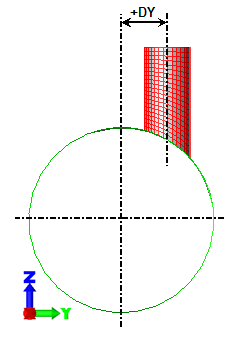
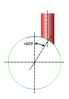
Offset of nozzle by distance Offset of nozzle by angle Figure 1: Offset of Nozzle For both cases, the nozzle can be rotated about the Y axis so that it is not parallel to the Z axis. Specify the angle in the Angular rotation of nozzle about Y-axis (AR) field. Note that this value follows the left-hand rule, so a negative angle rotates the nozzle about the +Y axis.
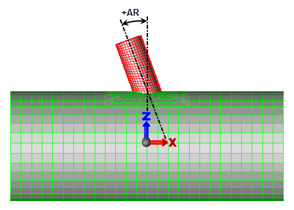
Figure 2: Rotation of Nozzle About Y Axis
A positive angle is shown. Note that the angle follows the left-hand rule.
The length of the nozzle, inside and outside of the cylinder, are specified on the Geometry tab using the Length of nozzle (L2) and Nozzle's length inside cylinder fields, respectively.
Nozzles on Heads
After a head is added to the main cylinder or to a nozzle on the main cylinder (see below), a nozzle can be added to the head! On the Heads dialog where the head is defined, activate the check box Include nozzles on head, and then click the Nozzles on head button. Refer to the page Nozzles on Heads for details.
Flanges, Repads, and Feature Regions
Flanges can be added at either end of the cylinder and at the end of the nozzle. Repad can be added at the intersection of the nozzle and cylinder. The widths of these features can be specified in the Flanges/Repad tab. Activate the check boxes for the features that you want to add and specify the desired width in the corresponding field.
A feature region is a layer of elements surrounding the nozzle and cylinder intersection (see Figure 3). It could be used for additional reinforcement, a region of constant width, or as a region to hide/show the elements and stresses near the intersection. The following steps are used to create a feature region:
- Go to the Model
 Mesh command.
 - Set the Meshing method drop-down to All increments specified.
- Use the Feature Region tab to enable and then set the dimensions and part numbers for the feature regions.
- Once the feature region is enabled, the Meshing method drop-down can be changed to another method if desired.
Add Heads to the Cylinder and Nozzle
If the pressure vessel has heads on either end of the cylinder or on the nozzle, specify these with the Model Heads dialog. See the page Heads Dialog for details.
Set Part Numbers
Each piece of the vessel - cylinder, nozzle, repads, and so on - can be created on a different part number. Recall that the part number controls parameters such as the material properties, and for plate/shell models, the thickness of the part and which side is top and bottom for pressure loading.
You can control the part number into which each piece is placed in the Parts dialog by accessing the MODEL pull-down menu and selecting the Parts command. When creating a solid mesh, use the Solid mesh composed of drop-down on the General tab to choose between creating the solid mesh on a single specified part number or on multiple parts.
Set Mesh Density
You can control the mesh spacing used for each part of the pressure vessel in the Mesh Parameters dialog by accessing the MODEL pull-down menu and selecting the Mesh command. When the Meshing method drop-down is set to Only transition parameters NHTX specified or Only transition parameters NHTT specified, you will only be able to control the mesh size in one direction (NHTX or NHTT) of the transition area where the nozzle meets the cylinder. The rest of the mesh is based on the single input for the transition region mesh size.
To control the mesh in all areas of the model, select the All increments specified option in the Meshing method drop-down box. Go to the appropriate tab for the mesh that you want to specify.
Most of the input is a straight forward number of how many elements are desired along a particular dimension. Those numbers then propagate to other areas of the vessel. For example, NHTT and NHTX determine how many elements are around the perimeter of the nozzle and any head placed on the nozzle. (See Figure 3.) Other parameters on the Mesh Parameters dialog are clarified below.
- The Transition Size tab controls how large the transition region is around the nozzle. (See Figure 3.) Separate controls are used for the axial direction and the sweep (or hoop) direction. When the Extent in _ direction defined using is set to Ratio, then the ratio of the size of the transition region to the intersection is specified. The extent ratio equals NX/diameter of nozzle and NT/diameter of nozzle (for the axial and hoop directions, respectively). If a repad or feature region is included, then the lengths NT and NX are outside the repad or feature region, whichever is larger. When no repad or feature region exists, then the lengths NT and NX are measured from the nozzle. When the Extent in _ direction defined using is set to Absolute _, the inputs of Axial direction length and Sweep direction angle correspond to NHTX and NHTT, respectively. Tip: In addition to creating a structured mesh by setting the parameters on the Mesh tab, a nonstructured mesh can be created if you own the ability to mesh CAD models. Use the PVDesigner File Export command and set the Save as type to Solid (*.igs). Then after exiting PVDesigner to return to Autodesk Simulation, use the
 Open command and set the Files of type to IGES. Once the IGES file is opened, set the mesh type as appropriate (either Solid or Plate/shell) and mesh the model.
Define Thickness
If you are creating a brick model, the thickness of each part can be specified in the Solid Thickness dialog by accessing the MODEL pull-down menu and selecting the Thickness command. (For plate/shell meshes, the thickness of each region is specified in the FEA Editor under the Element Definition.)
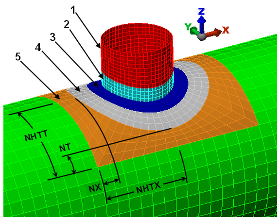
Figure 3: Transition Mesh Between Nozzle and Cylinder
Key:
1 = nozzle mesh
2 = optional feature region on the nozzle
3 = optional feature region on the cylinder
4 = optional repad on the cylinder
5 = transition region on the cylinder
NHTX = half the axial length of the transition region
NX = distance between nozzle (or repad or feature region if it exists) and end of transition region in the axial direction
NHTT = half the sweep length of the transition region
NT = distance between nozzle (or repad or feature region if it exists) and end of transition region in the sweep direction