The 2D mesh generator is an advanced tool for automatic mesh generation of any enclosed region drawn in any plane. This generator allows you to automatically mesh fairly complicated regions with one simple command. The 2D mesh generator offers mesh refinement options which allow you to quickly and easily refine your mesh by putting more elements at critical points in your design.
The general process is as follows:
- Create a sketch of the wire frame (or outline) of each part. Each wire frame must be
- composed of construction objects (not regular lines),
- must form a continuous, enclosed region with any number of internal holes, and
- each region within a given plane must be drawn on a different part. (See Drawing Planes for more information.)
- Optionally, set the surface number of the construction objects to aid with applying multiple loads and boundary conditions to the part. (By default, each edge of the mesh is on a unique surface number, but the mesher has an option to assign the surface number of each edge based on the construction object's surface number.) Tip: To have a node appear at a specific location on the wire frame, split the wire frame at that location. The 2D mesh generator creates nodes at each endpoint of the construction objects. For example, to place a node at the 30 degree position on the perimeter of a hole, draw a temporary construction line that intersects the circle at that position, and then use Draw
 Modify Intersect to split the circle.
- Specify edge divisions and refinement points if desired. See Specify Edge Divisions and Refinement Points for more information.
- Once all of the sketches are complete, you can generate the 2D mesh by selecting the drawing plane under each part headings in the tree view, right-clicking, then choosing the Create 2D Mesh command. The 2D Mesh Generation screen will appear. All parts on a given plane should be meshed together to assure that the meshes match between the parts. Different planes are meshed separately. For information on the options in this screen, see Generate 2D Meshes. Tip: Instead of selecting multiple sketches individually, you can right-click the drawing plane entry under the Planes heading in the tree view and choose Select all Sketches. This highlights each sketch under the parts in the tree view associated with the drawing plane. Deselect sketches that are not to be meshed.
To use the 2D mesher, the construction objects must be drawn in a sketch on a drawing plane; they cannot be 3D objects which are a separate branch of the tree view. 3D objects cannot be used in the 2D mesher even if they lie in the same plane as other sketch objects. Click the sketch in the tree view to see the objects belonging to the sketch.
Using Multiple Parts and Planes:
The 2D mesh generator will mesh one plane at a time. When working with assemblies consisting of multiple parts within the plane, it is important to remember that each part must consist of a single enclosed area. Figure 1 below shows some valid and invalid regions.
|
(a) Valid Region - with three holes |
(b) Invalid Region - break in outer boundary |
|
(c) Invalid Region - break in inner boundary |
(d) Invalid Region - intersecting boundaries |
|
(e) Invalid Region - touching boundaries |
(f) Invalid Region - touching boundaries |
|
Figure 1: Example Sketches for Purposes of 2D Mesh Generation |
|

Imagine that the three holes in Figure 1(a) are to be filled with another material (and for discussion, assume that everything shown in the figure is drawn on part 1). A rectangle drawn on part 2 and over top of the rectangular hole in part 1 would fill the rectangular hole. A circle would be drawn on part 3 to fill the circular hole, and a semi-circle would be drawn on part 4 to fill the semi-circular hole.
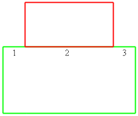
Another important situation for some analysis types is shown in Figure 2.
- For analysis types that do not support smart bonding, when two parts are meshed together, each part must have a matching segment for the mesh to match at the interface. The top edge of the large rectangle must be drawn using three lines to ensure that the mesh along the shared edge matches up correctly.
- For analysis types that do support smart bonding, the parts do not need to have matching segments in the sketch. See the Types of Contact page for the analysis types that support smart bonding. Figure 2: Matching Between Parts without using smart bonding