Use the SpeedForm Face tool to start building almost anything.
SpeedForm Face tool Overview
Use the Face tool to define the initial profile to begin design and modeling process.
- The SpeedForm Face tool is flexible and essential for the initial modeling phase.
- Use the Face tool in to explore or with sketches and reference data.
- Use the Face tool at the very beginning of the process. It provides the foundation to build more surfaces.
Using SpeedForm core tools and functions in context
Tools used in this workflow:
- Edit Form move, rotate, scale, and extrude
- Face (multiple sides)
- Weld Vertices (midpoint option)
- Mirror Duplicate
- Crease and UnCrease
- Insert Edge Ring
Initial Design/Modeling phase
Use references to speed up the design 3D modeling process.
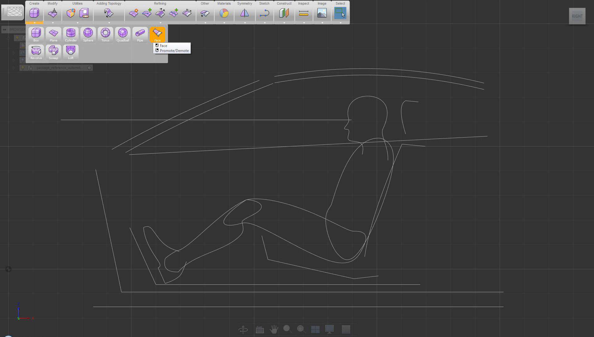
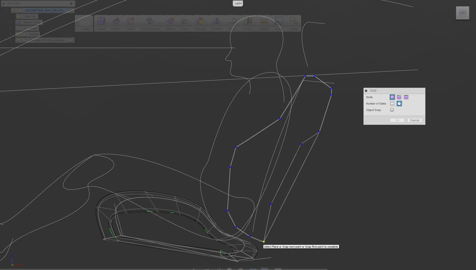
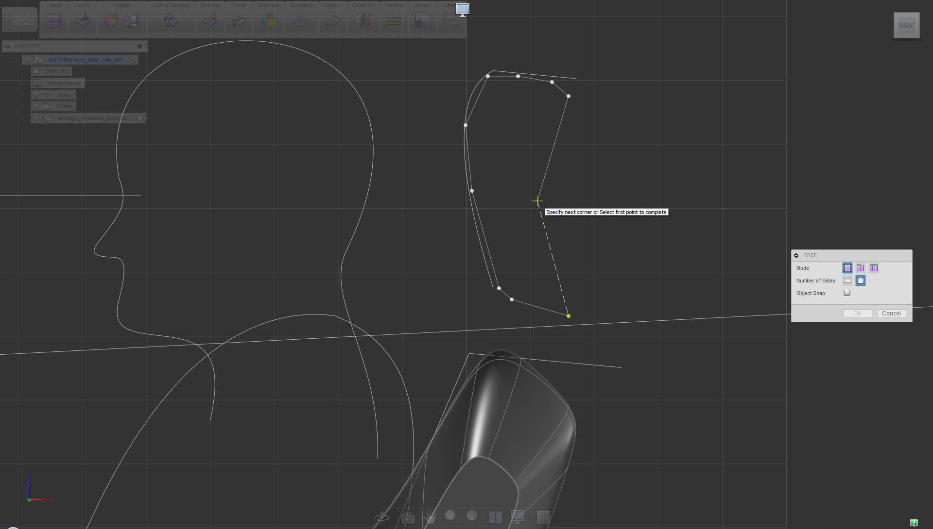
To begin, select the Face tool
Get to know which tools to use. For defining a profile, use multiple sides for flexibility.
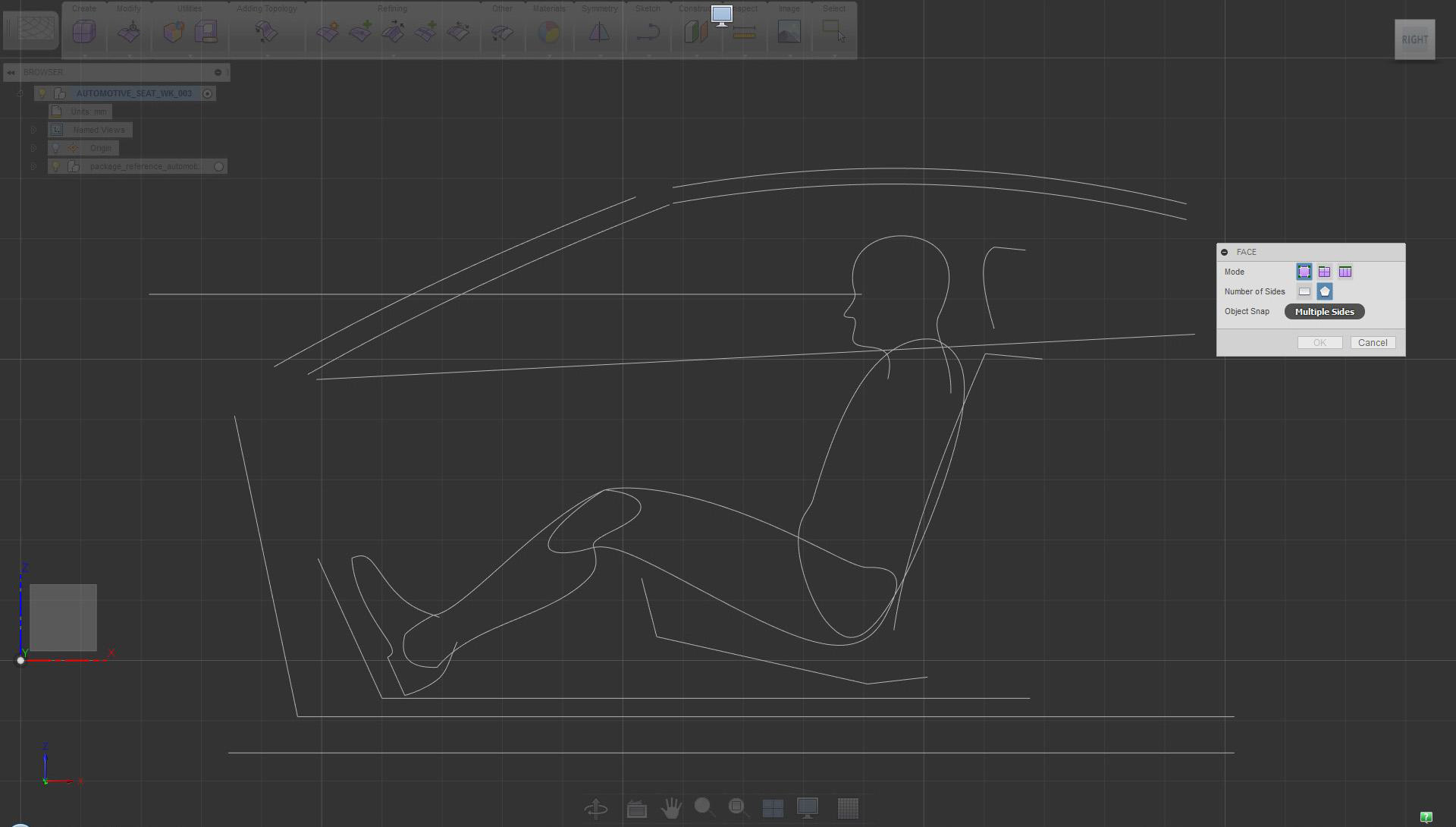
In orthographic side view, select the multiple sides option and click the XZ plane
Use more points in areas where definition is needed.
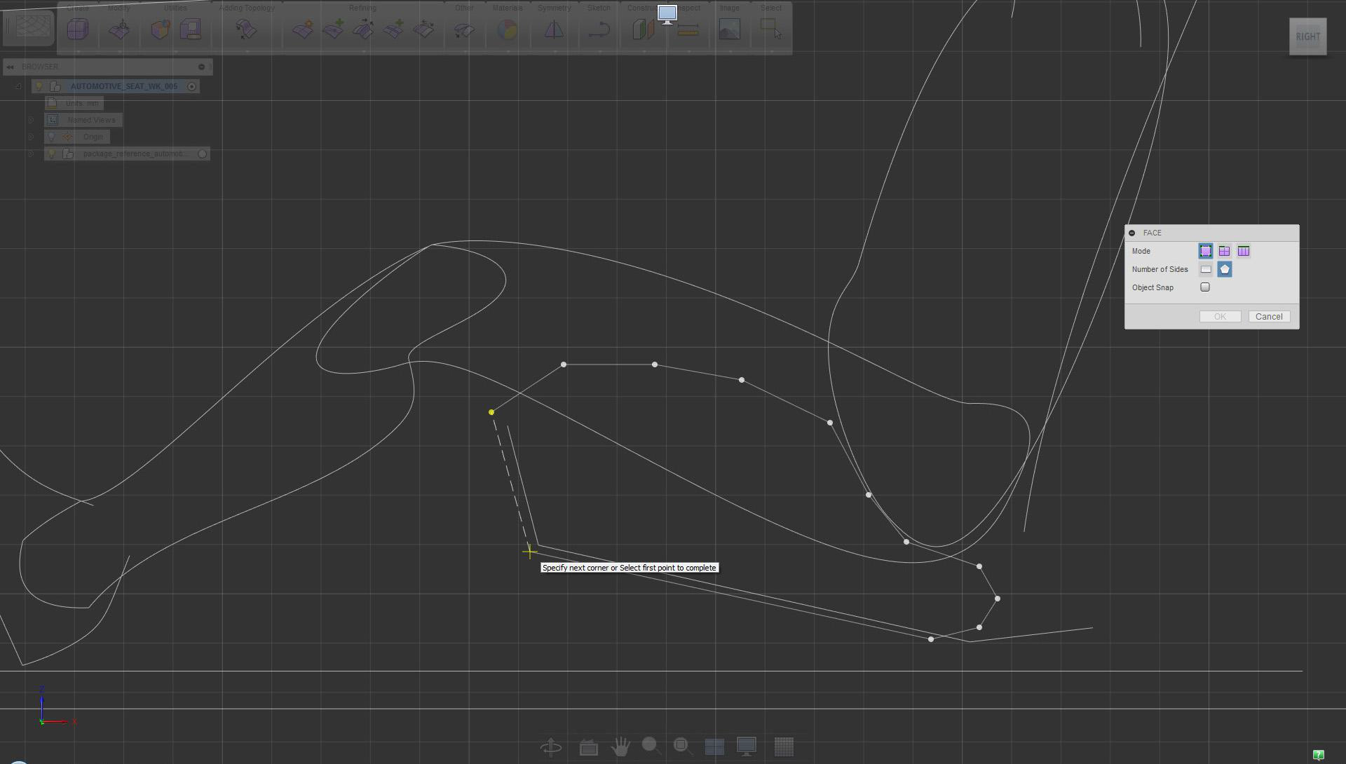
Place points to define the seat profile. Select the starting point when done.
Defining size and volume
Start moving objects to roughly define and decide on size and proportions.
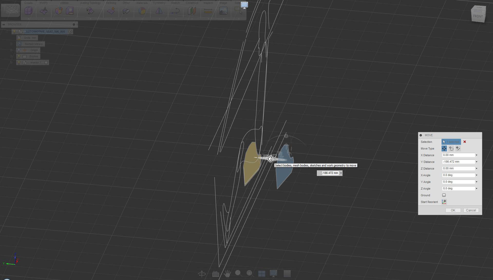
Use copy/paste to duplicate the newly created face, then move it in the -Y direction
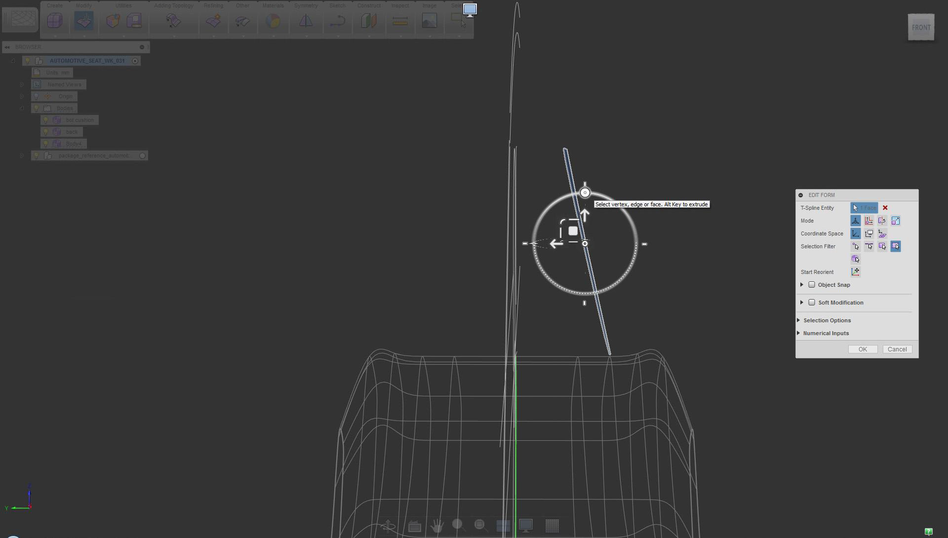
Adjust angles early. This is important for design, but it also helps the modeling process.
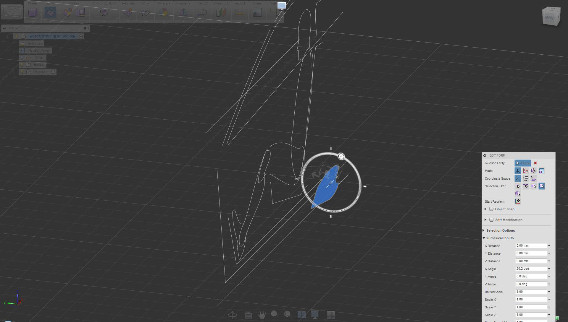
Rotate the face (X axis) to adjust the angle (this becomes the seat lower side panel)
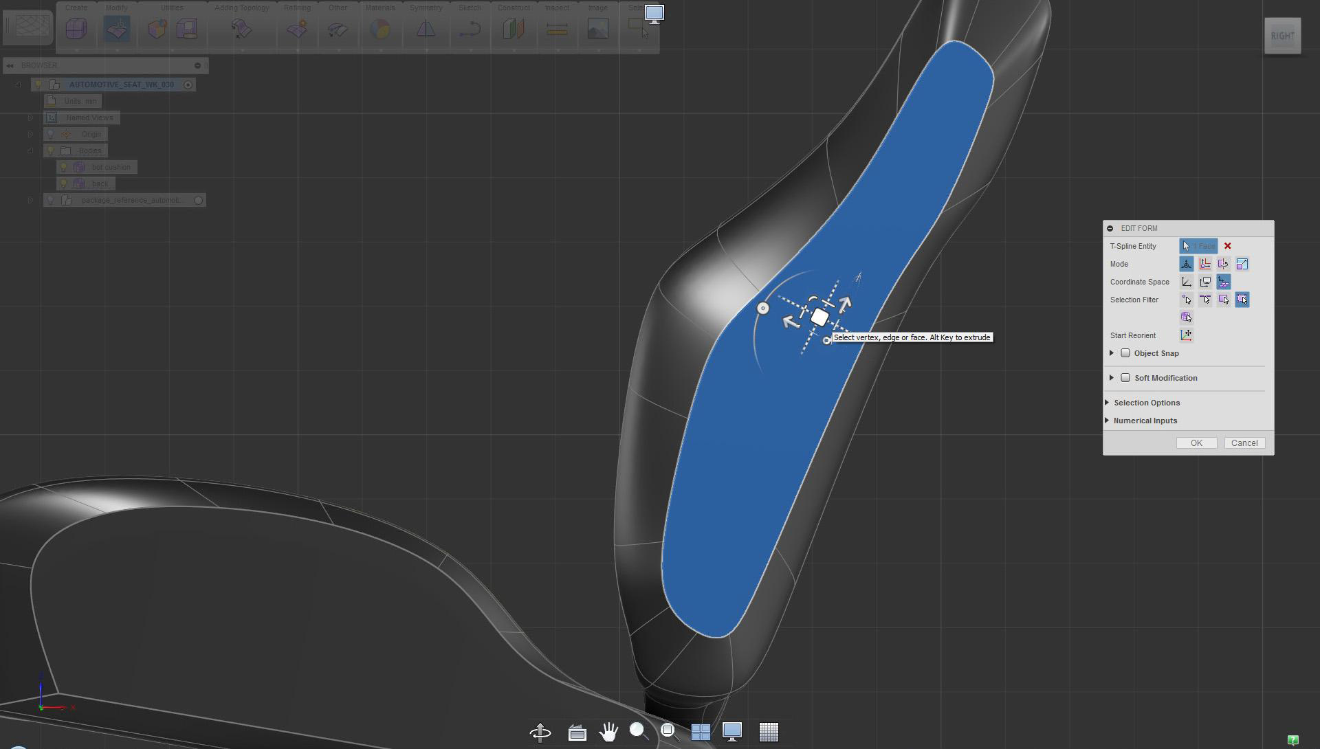
Start creating volumes after placing main surfaces.
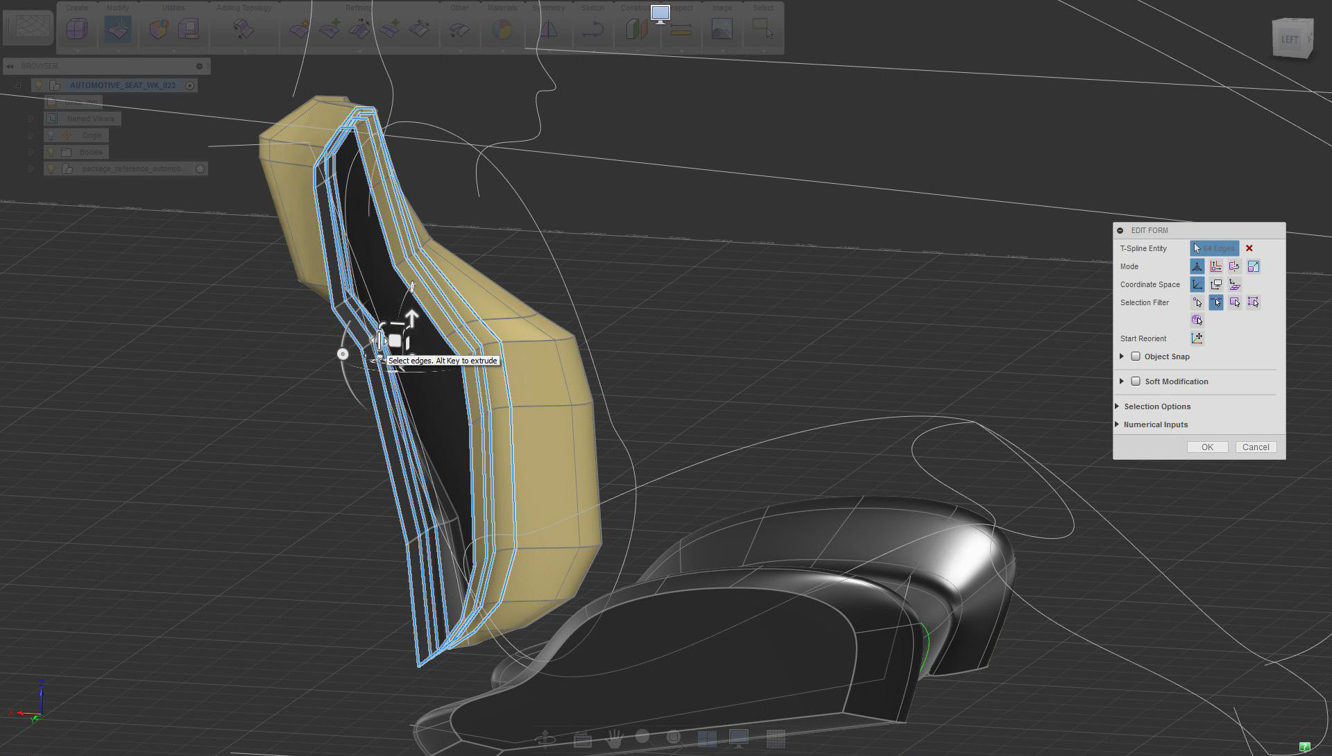
Select the face and use Edit Form extrude (maintain creased edges, Ctrl+Alt)
Continue creating a simple volume. Profile and details are modified later.
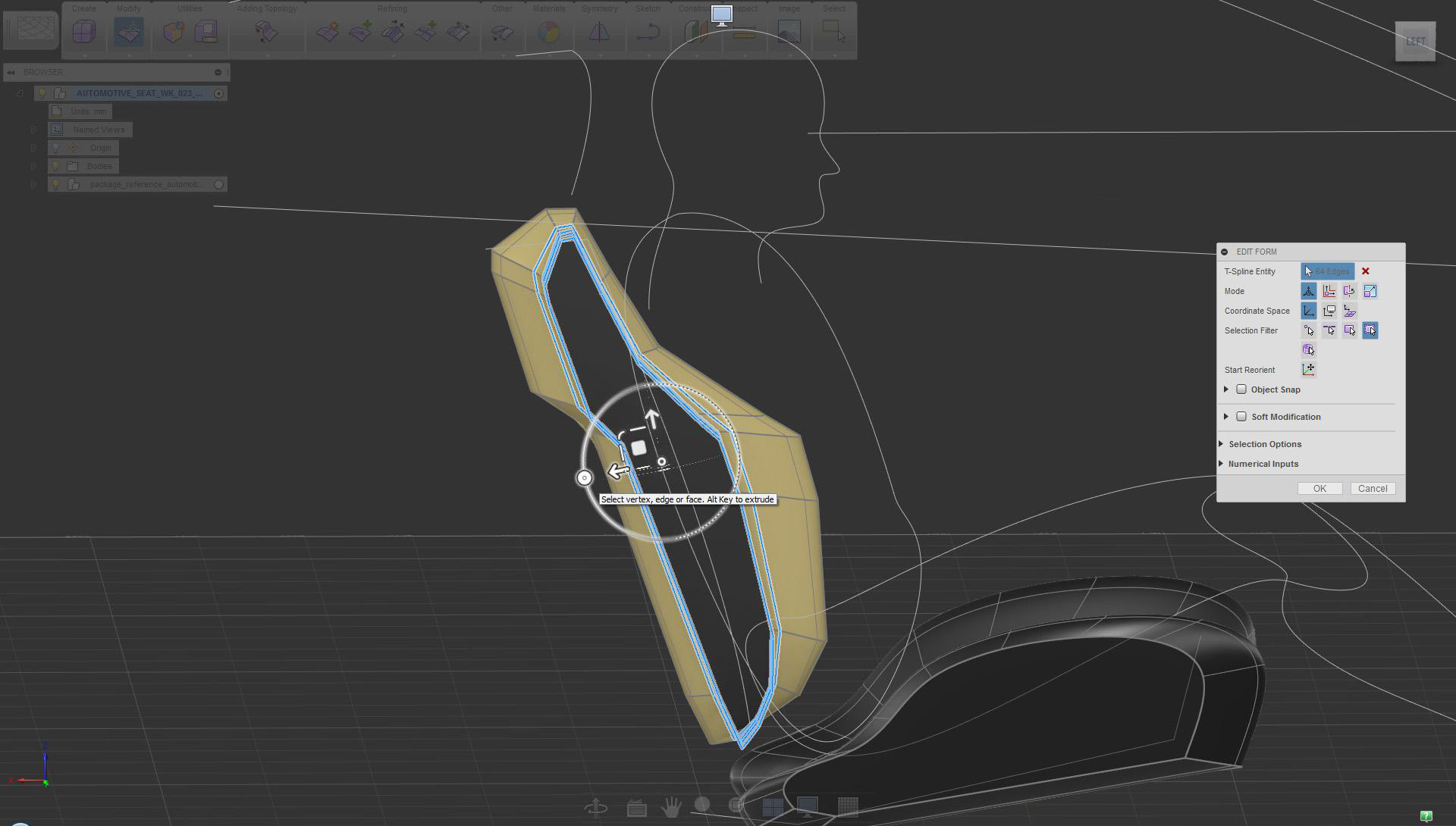
Keep using Edit Form extrude combining move and scale mode (no creased edges)
Size and proportions are not set yet.
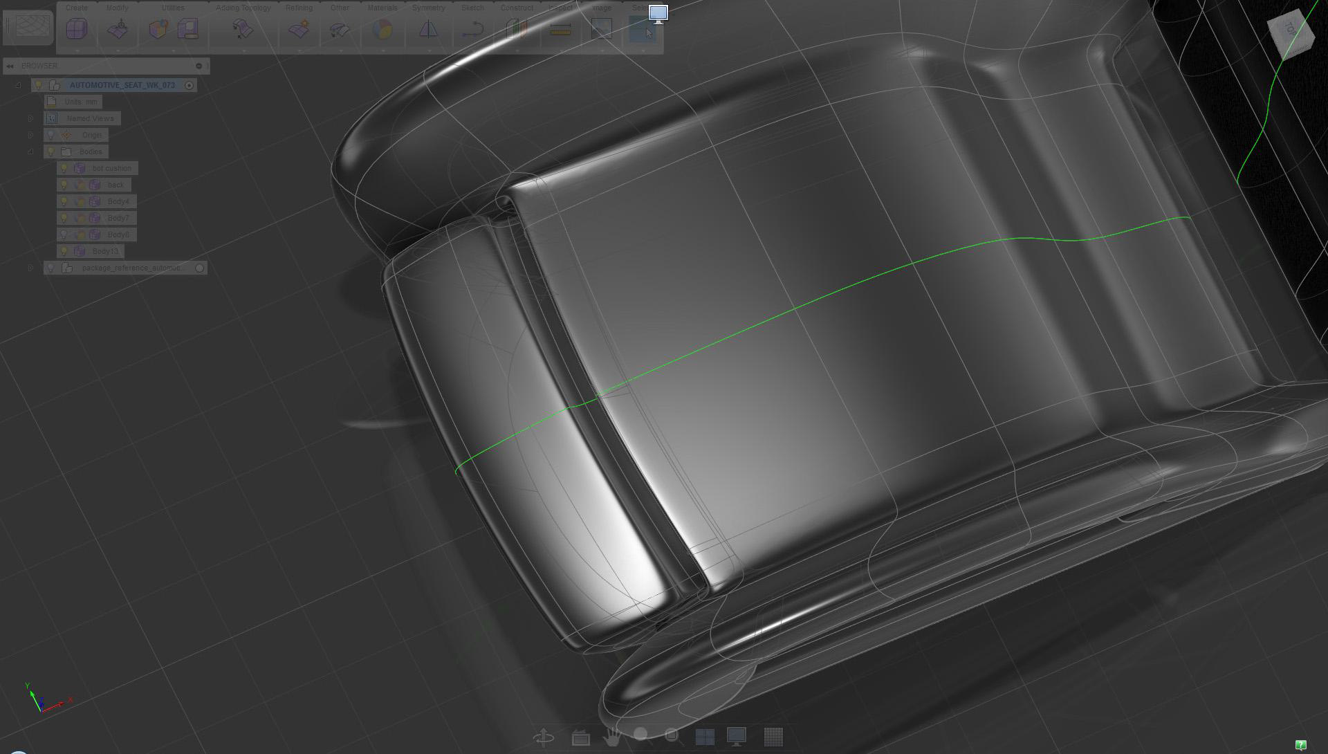
Switch to smooth shading mode (Alt+1) to examine the design
Before adding more a defined design, mirror and connect geometry.
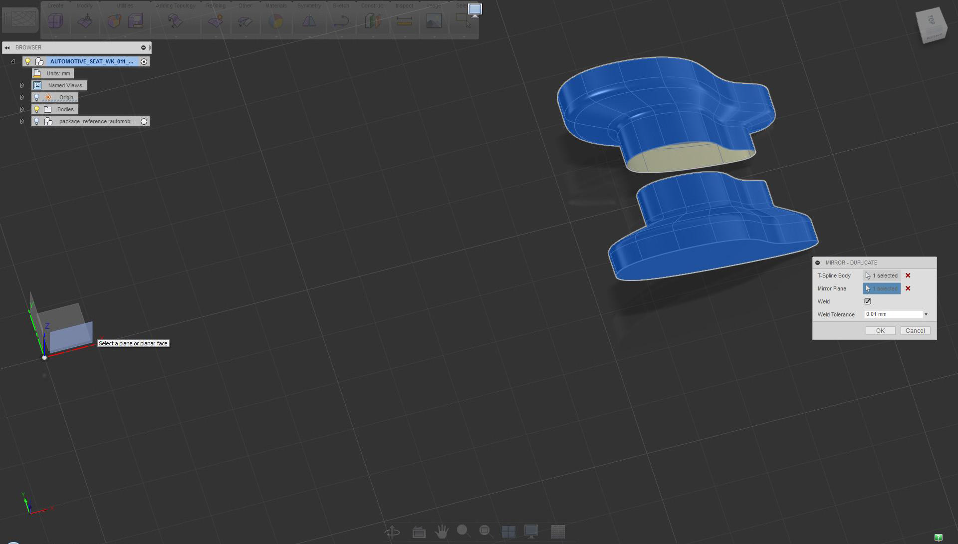
Use Mirror Duplicate to create symmetry across the XZ plane
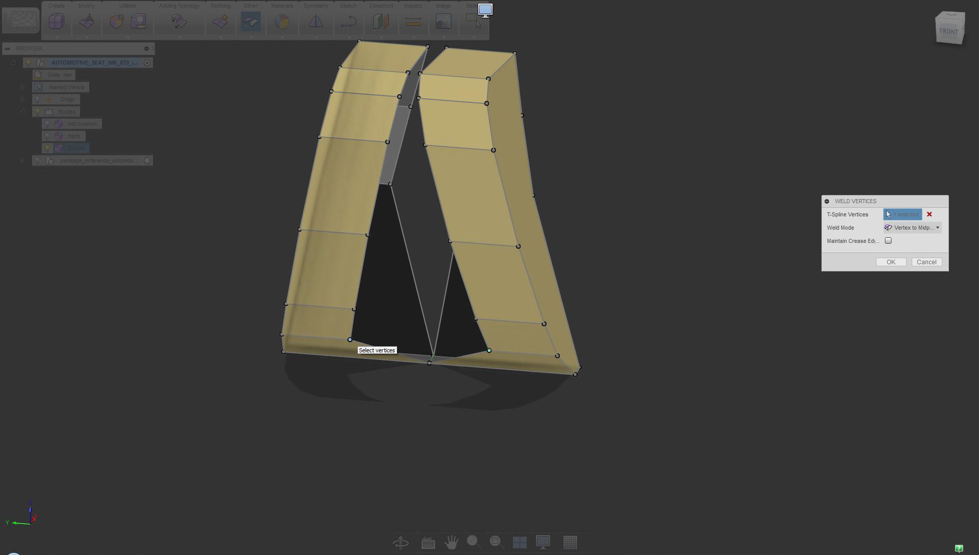
Operations such as Weld Vertices are best performed in box display mode.
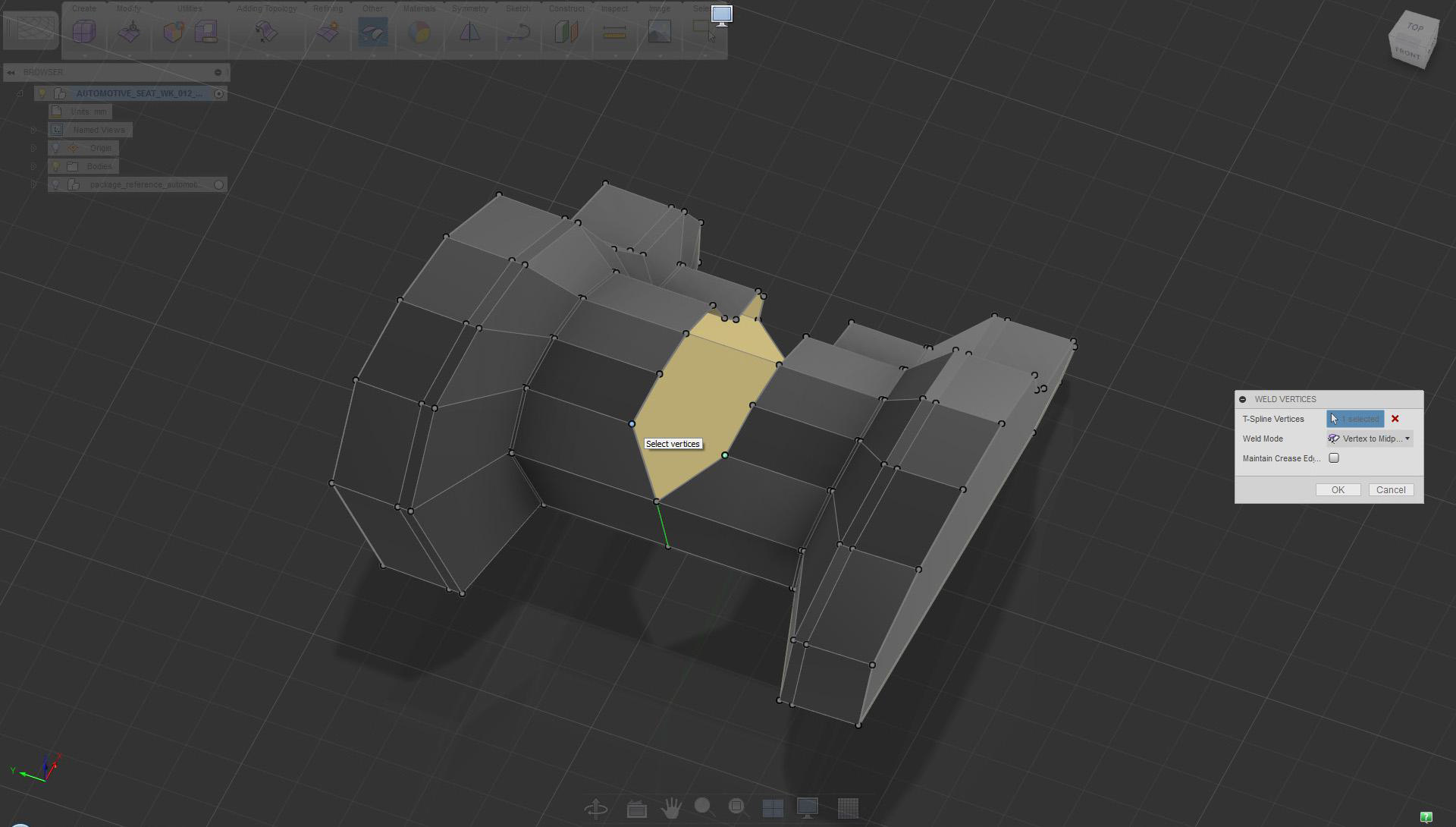
Switch to box display mode and use the Weld Vertices tool, midpoint option to join sides. Alternatively, use the Merge Edge tool.
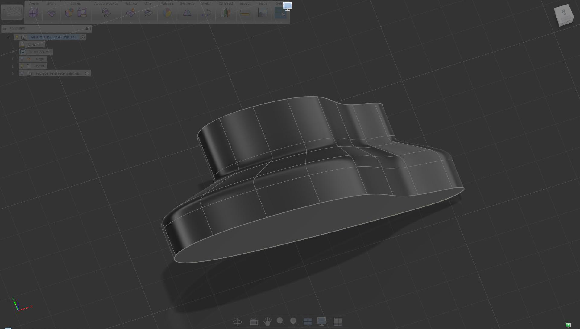
Once symmetry is established, it is easier to visualize and the change shape.
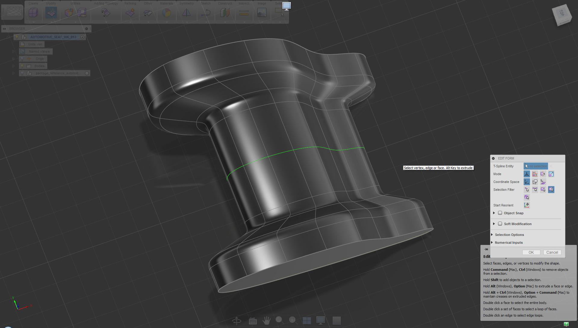
Current status shown in smooth shading mode
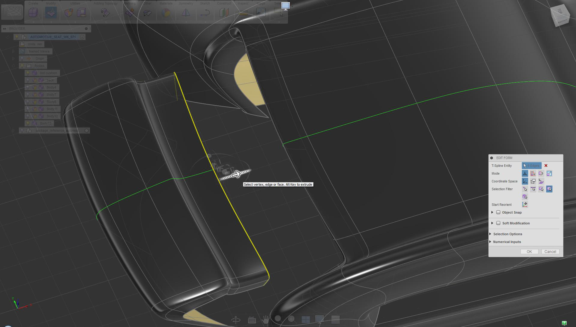
Adjust the size and shape by moving lines or faces.
Select and move the front edge horizontally to adjust design/proportions
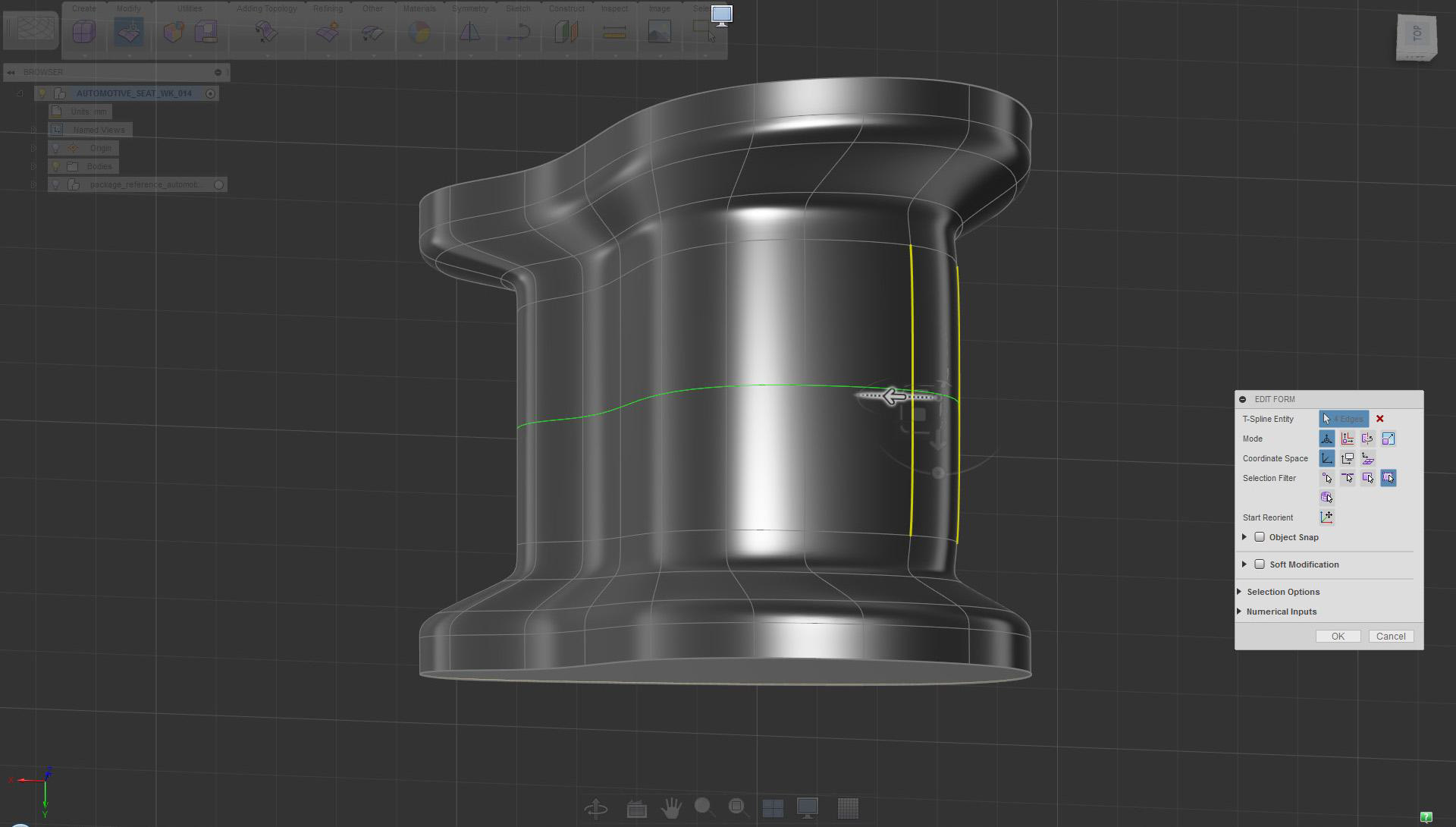
Balance the shape by working on various areas of the model.
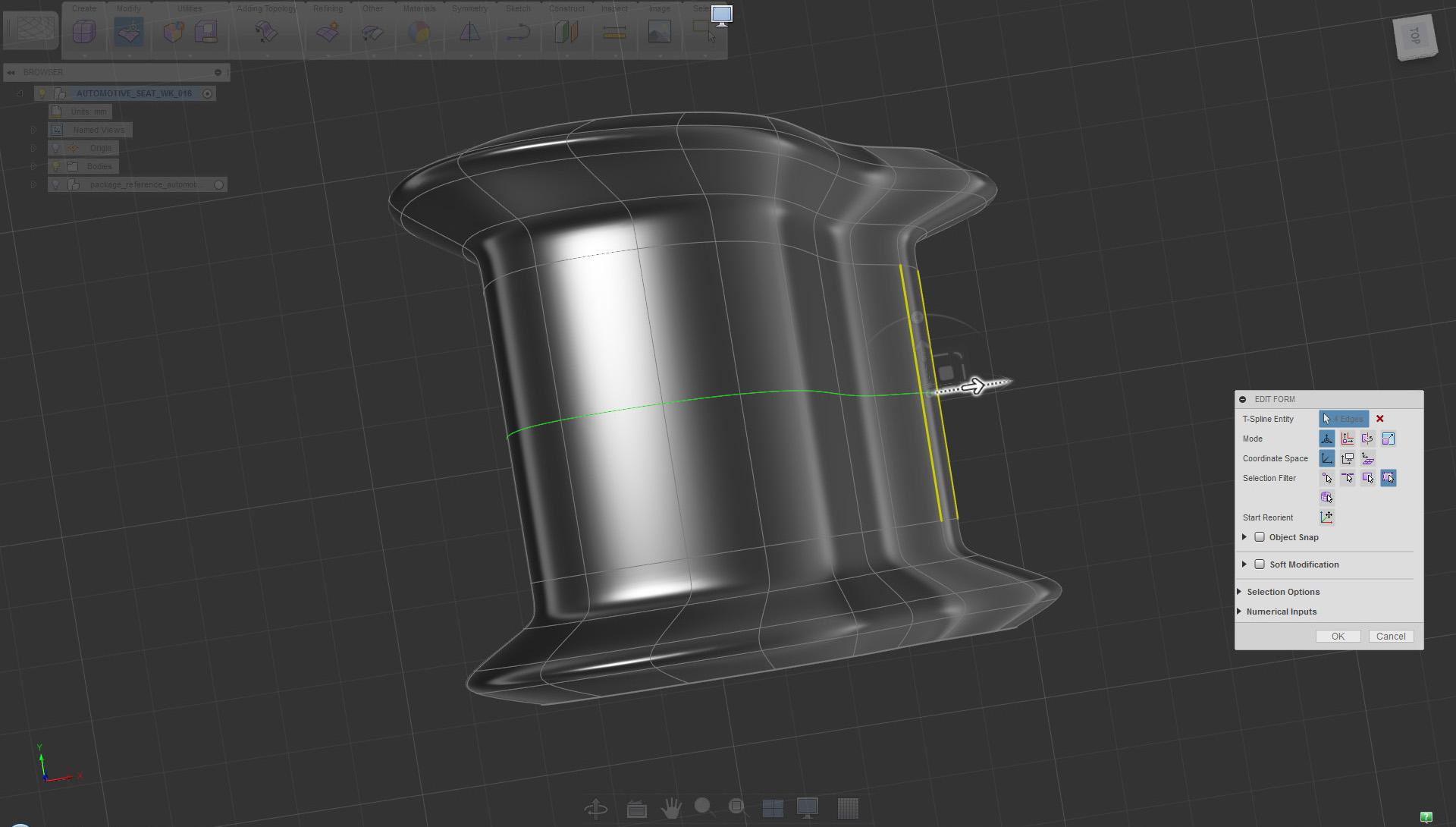
Select and move back the edge in a similar manner or as needed
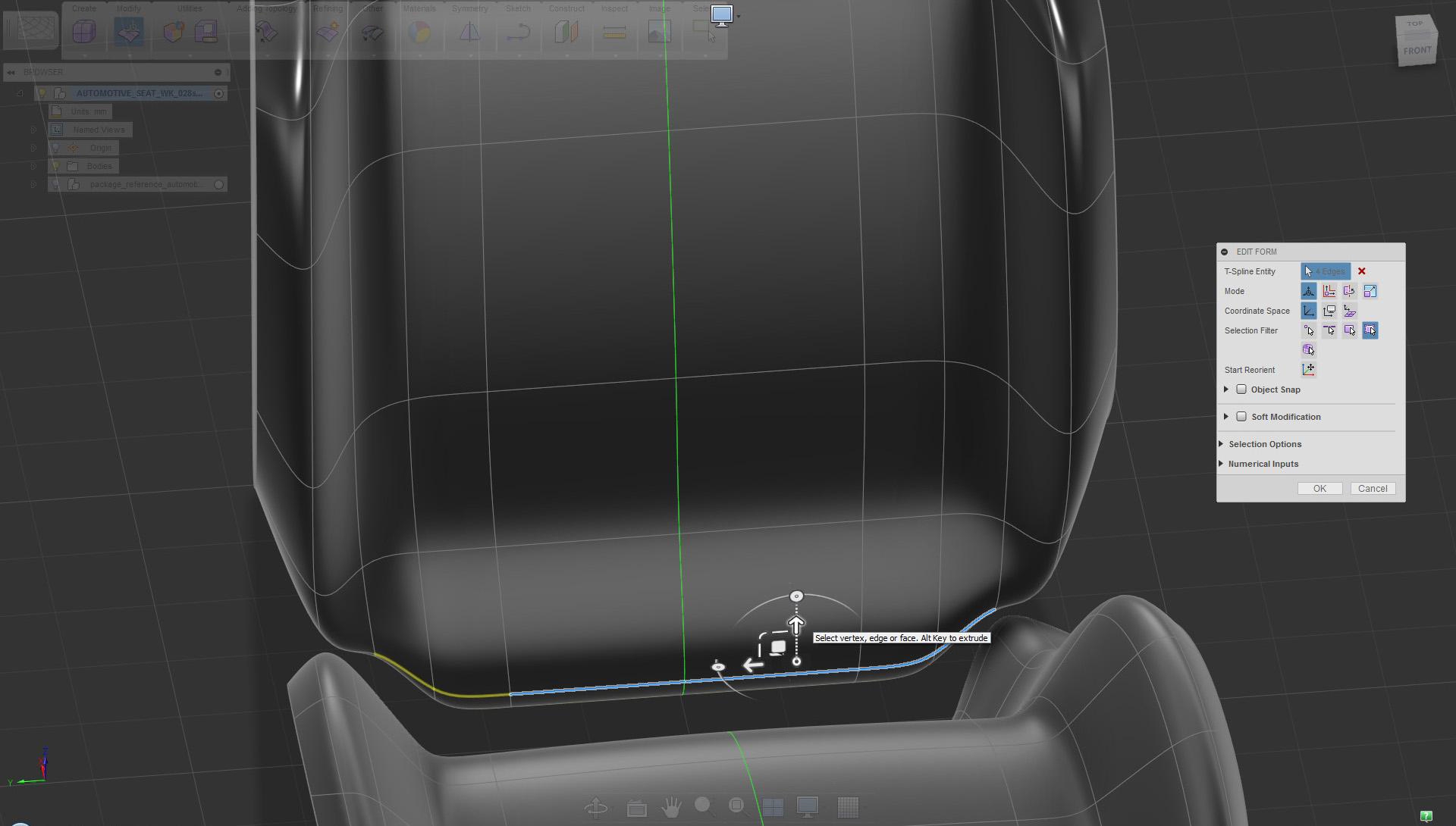
You can also change Shape by applying edge treatment.
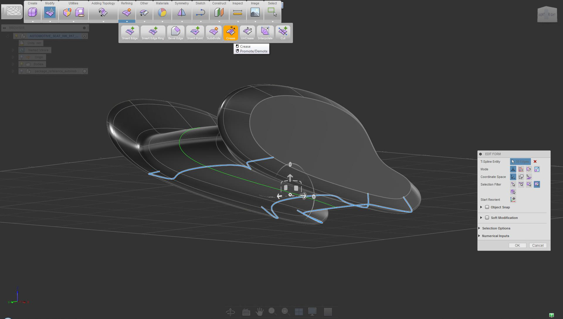
Select bottom edges and use the Crease tool to flatten the surface
Keep in mind the functionality of the design, and prioritize the workflow as early as possible.
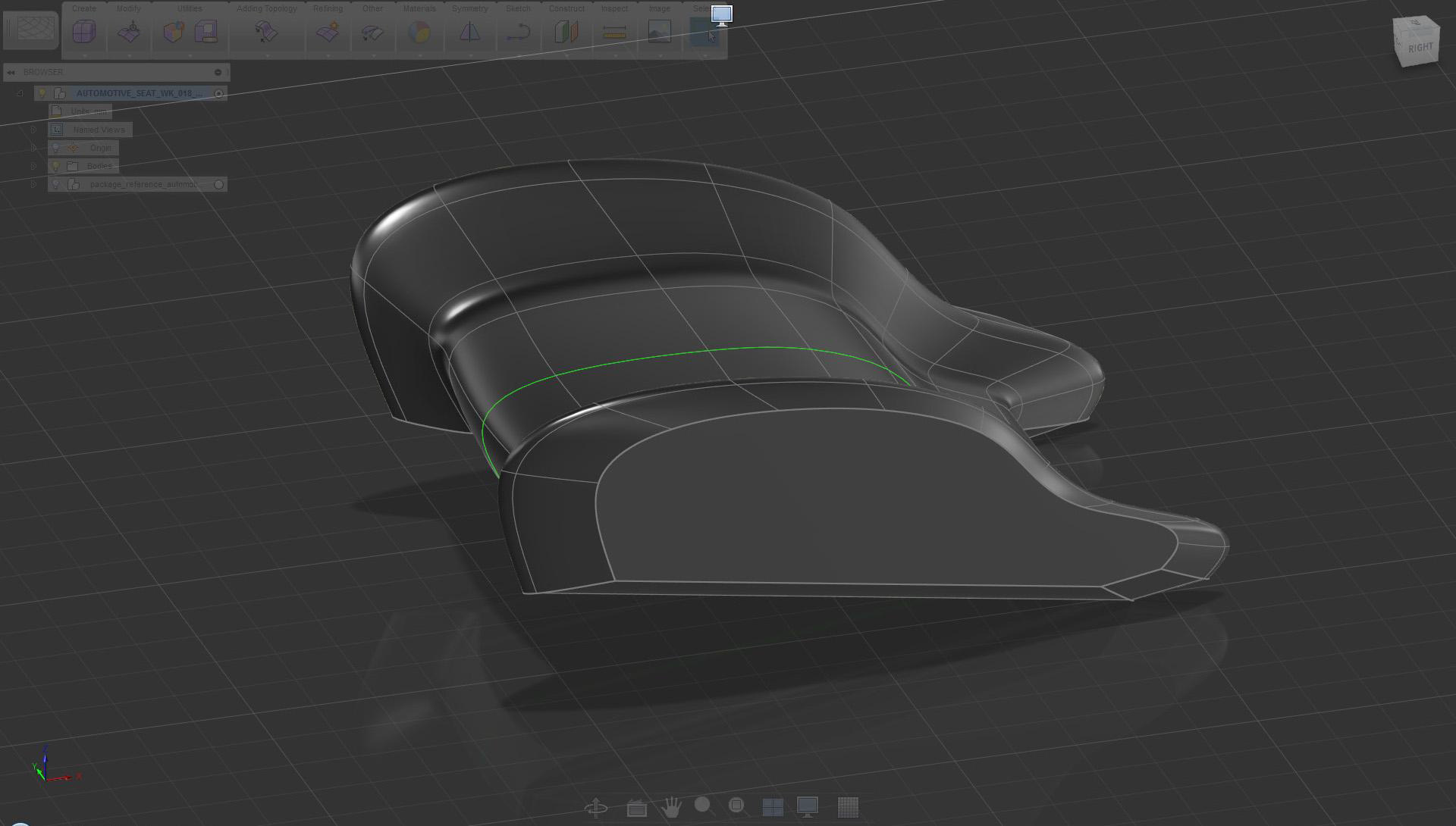
Bottom surface features straight running lines after the crease was used
Use common line treatment/theme when creating parts that belong to the same design.
Use the Face tool to define the profile for the side bolster and the back of the seat
Keep an overview of all parts in the scene (they should share common design language).
Apply Edit Form extrude (creased edges) to the newly created face. Refer to the seat bottom creation for detailed steps.
Again, keep an eye on references and adjust the form accordingly.
Use Rotate to adjust edges as needed
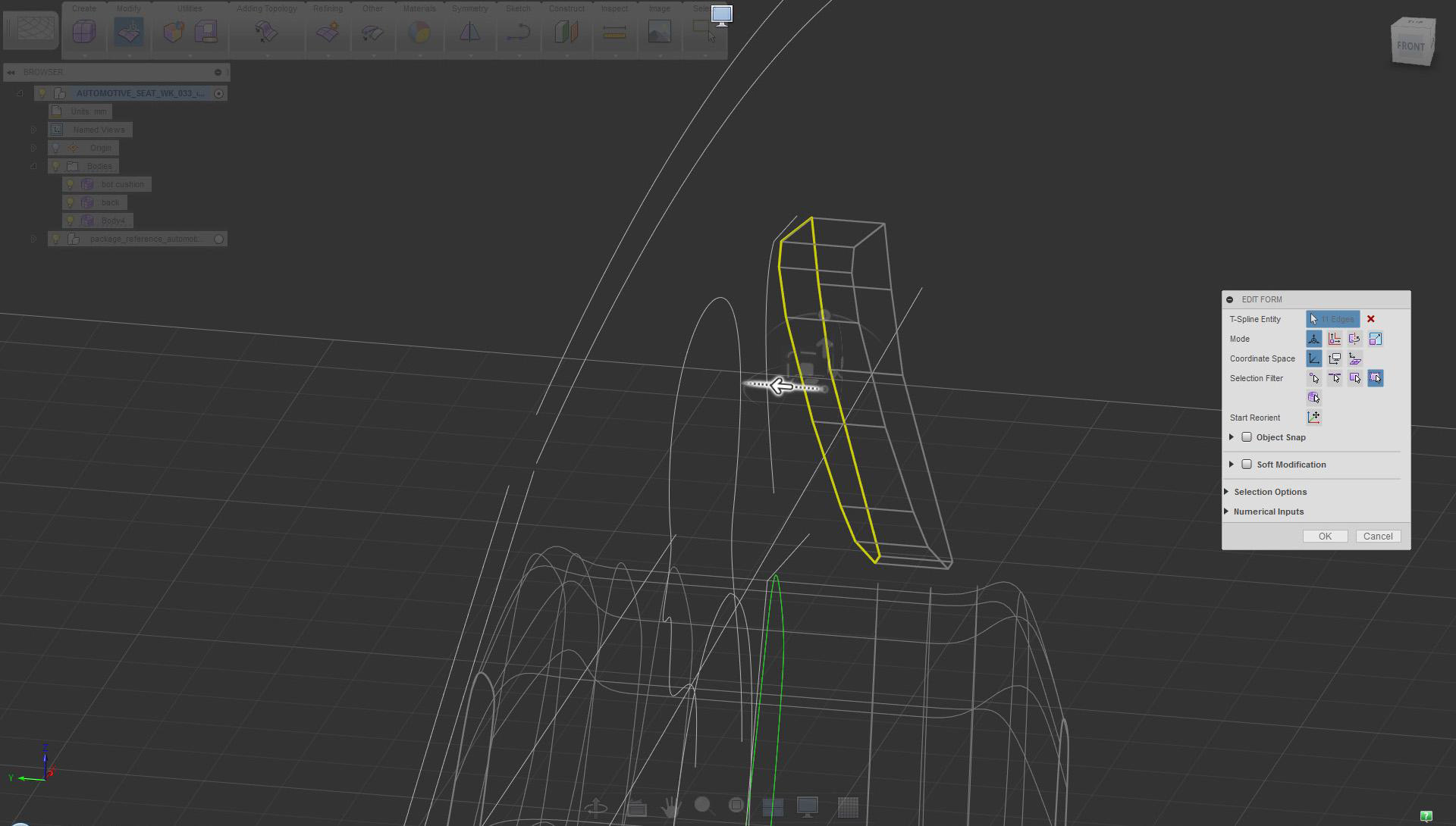
Modify parts so they come together in a meaningful way.
Pull edges to conform the shape to the seat bottom
Reduce volumes where not needed. The design should appear lean.
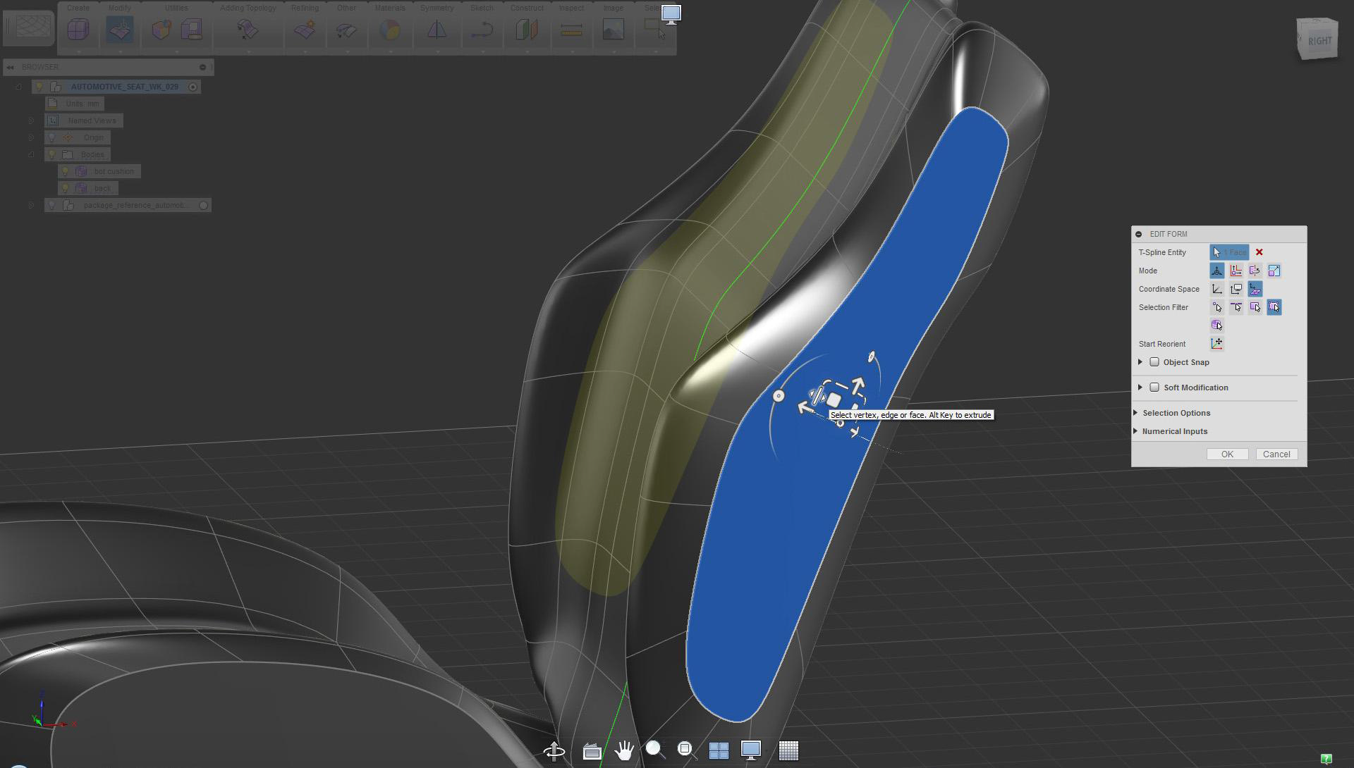
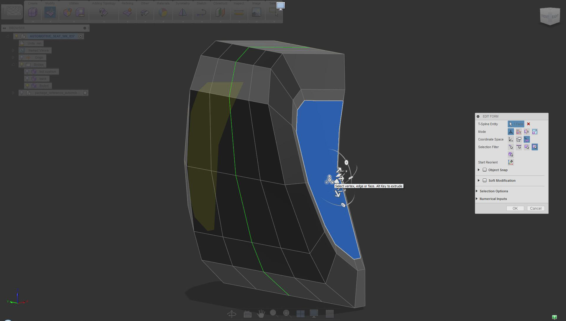
Scale side face as needed (Edit Form local option)
Start adjusting the proportion between surfaces in the side view.
Position the side face using Edit Form move in local space (option)
The section influences and can inspire design. Aim to make the “line” dynamic and clean.
Again, use the Face tool to define the headrest profile in the side view
Tapering volumes usually helps with design and function.
Tapering volumes usually helps with design and function.
It is beneficial to have volumes to work with. Create surfaces as soon as you can.
Edit Form extrude (creased edges: Ctrl+Alt)
Some essential tools are used all the time. Weld Vertices is one of these core tools.
Mirror object and join using Weld Vertices (midpoint option). Detailed process is explained earlier.
The Crease/UnCrease tools are used to create or remove sharp edges, respectively.
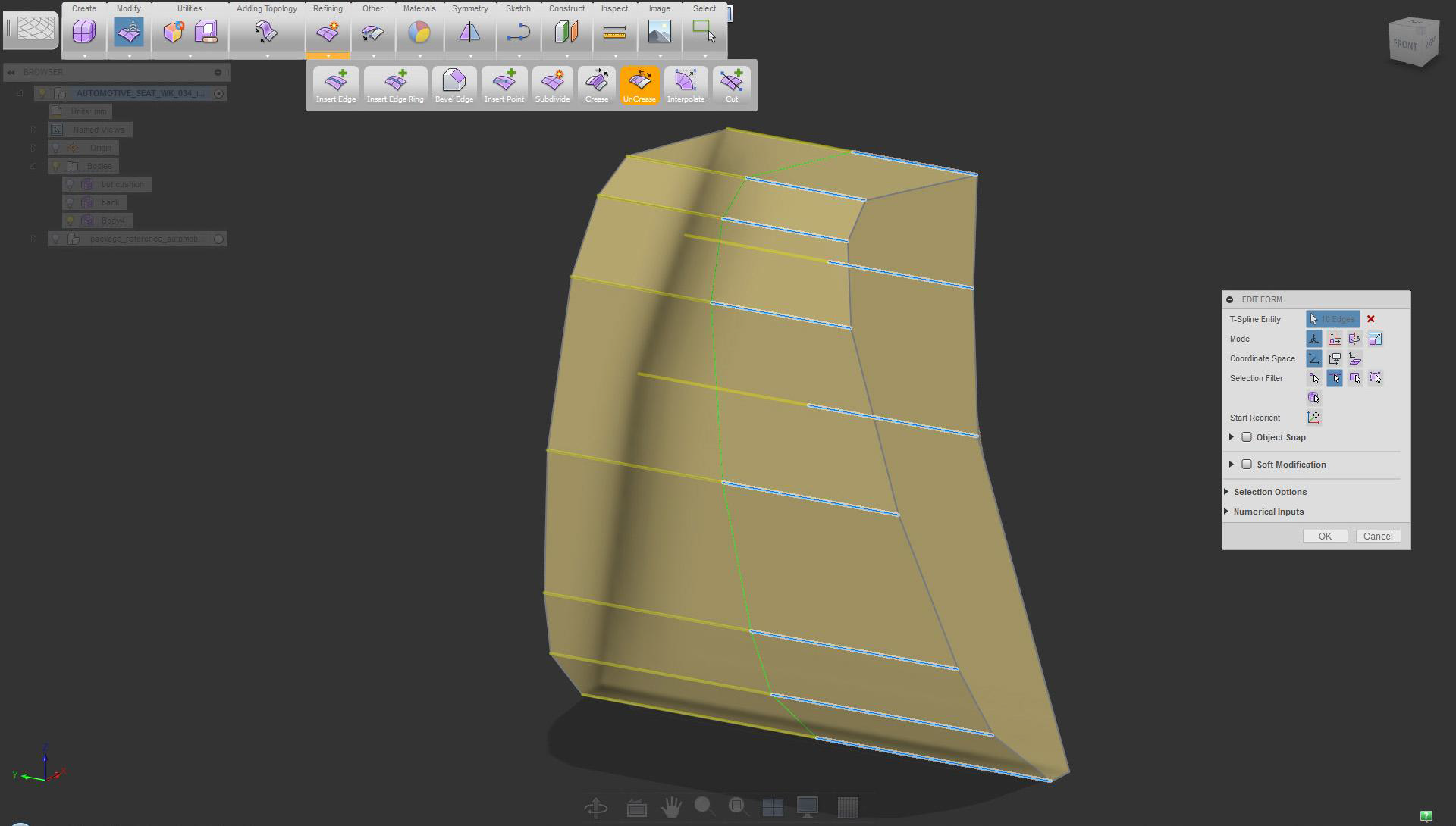
UnCrease only selected edges
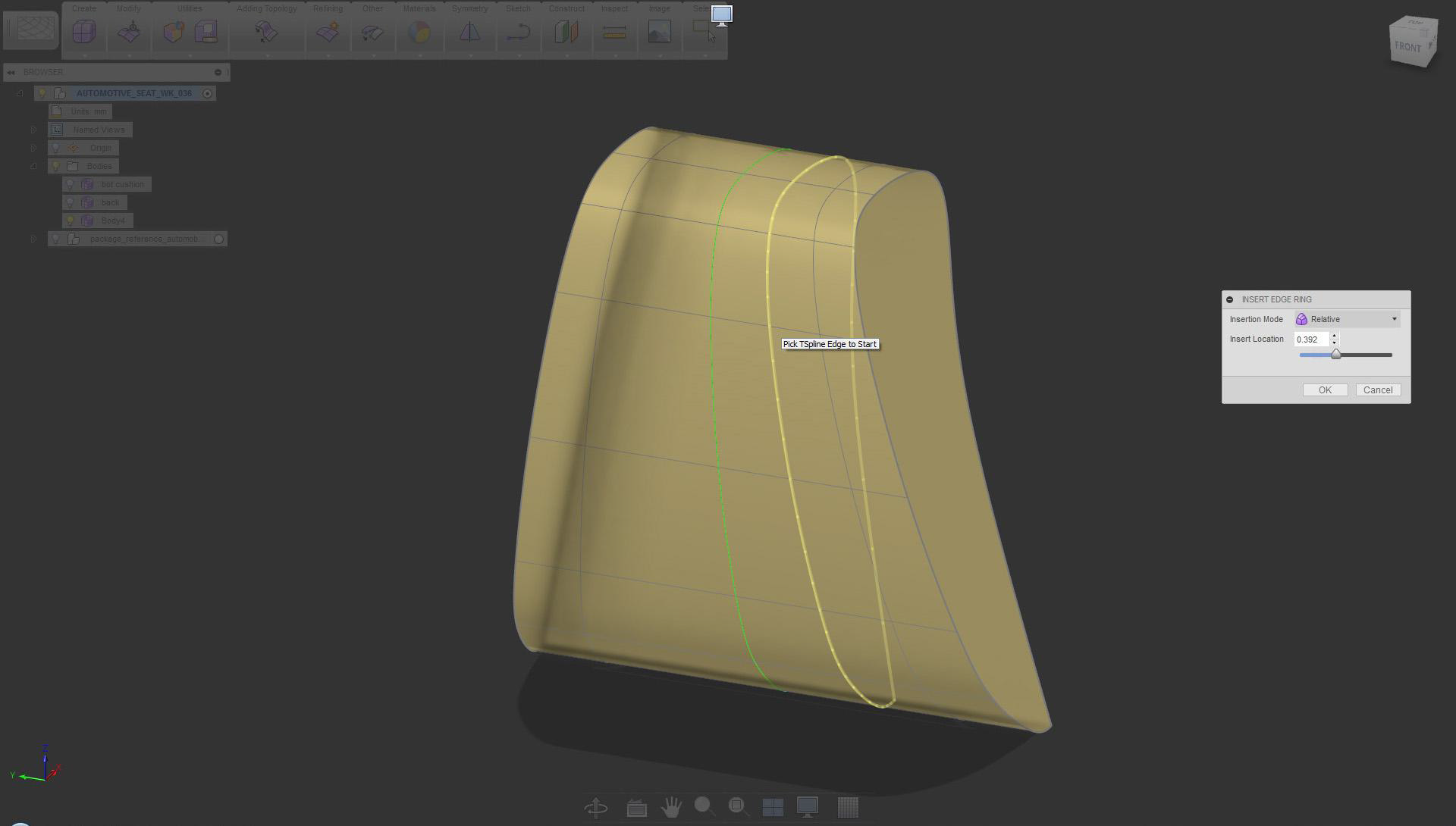
Apply Insert Edge Ring for more definition
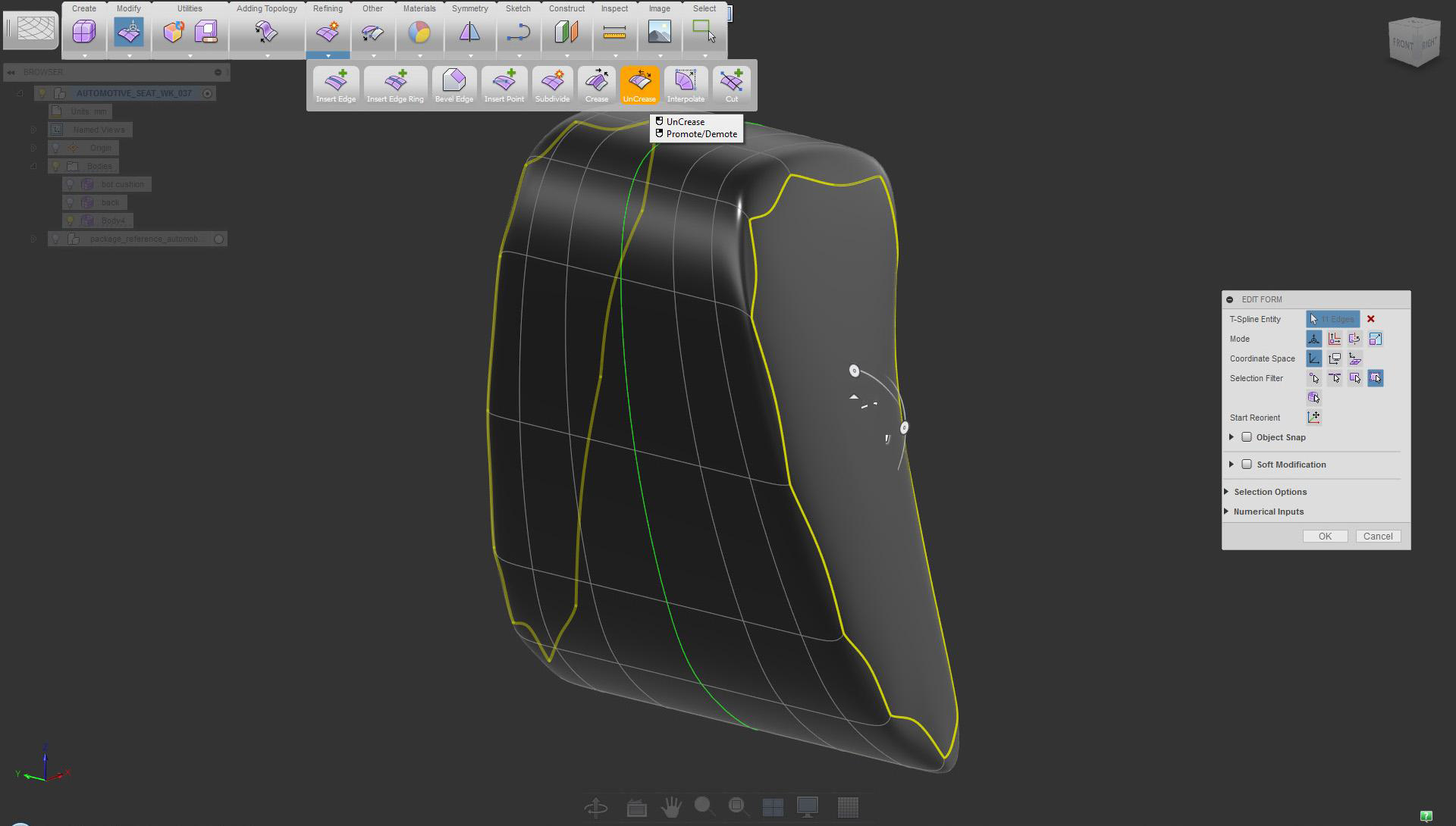
Again, use the UnCrease tool on the side edges of the headrest
Use Edit Form scale extrude (select local option, and hold Alt to extrude)
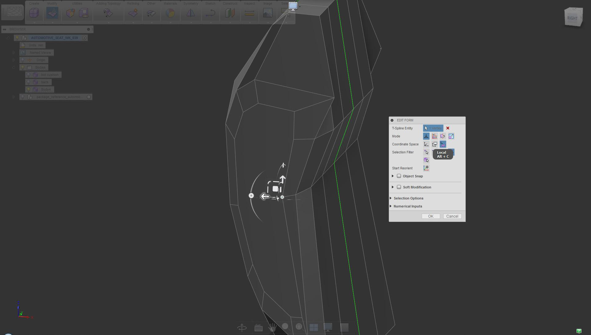
Adjust individual vertices (use local option not to distort the face)
Adding details
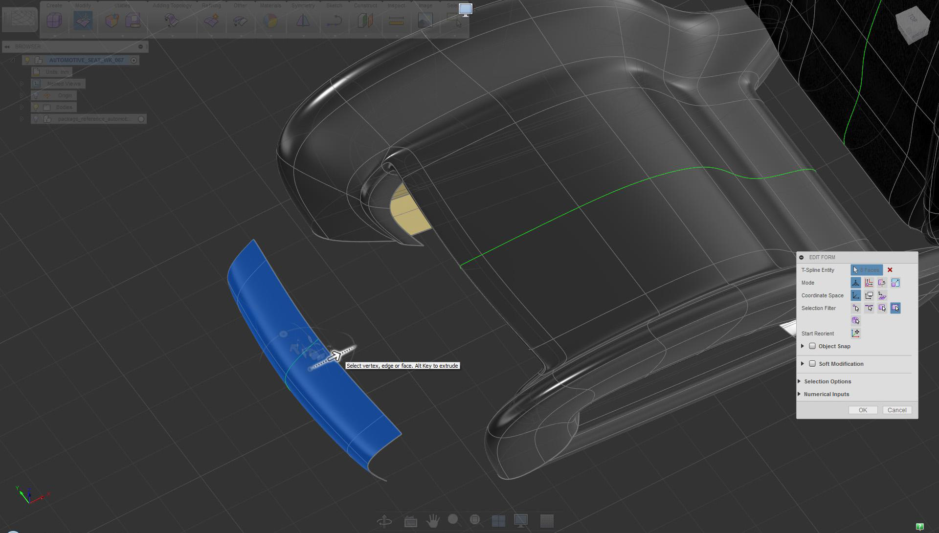
To create new geometry quickly, copy/paste existing surfaces.
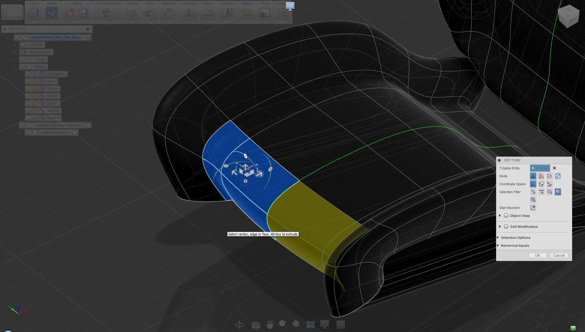
Select surfaces and use copy/paste to create duplicates
To create new geometry quickly, copy/paste existing surfaces.
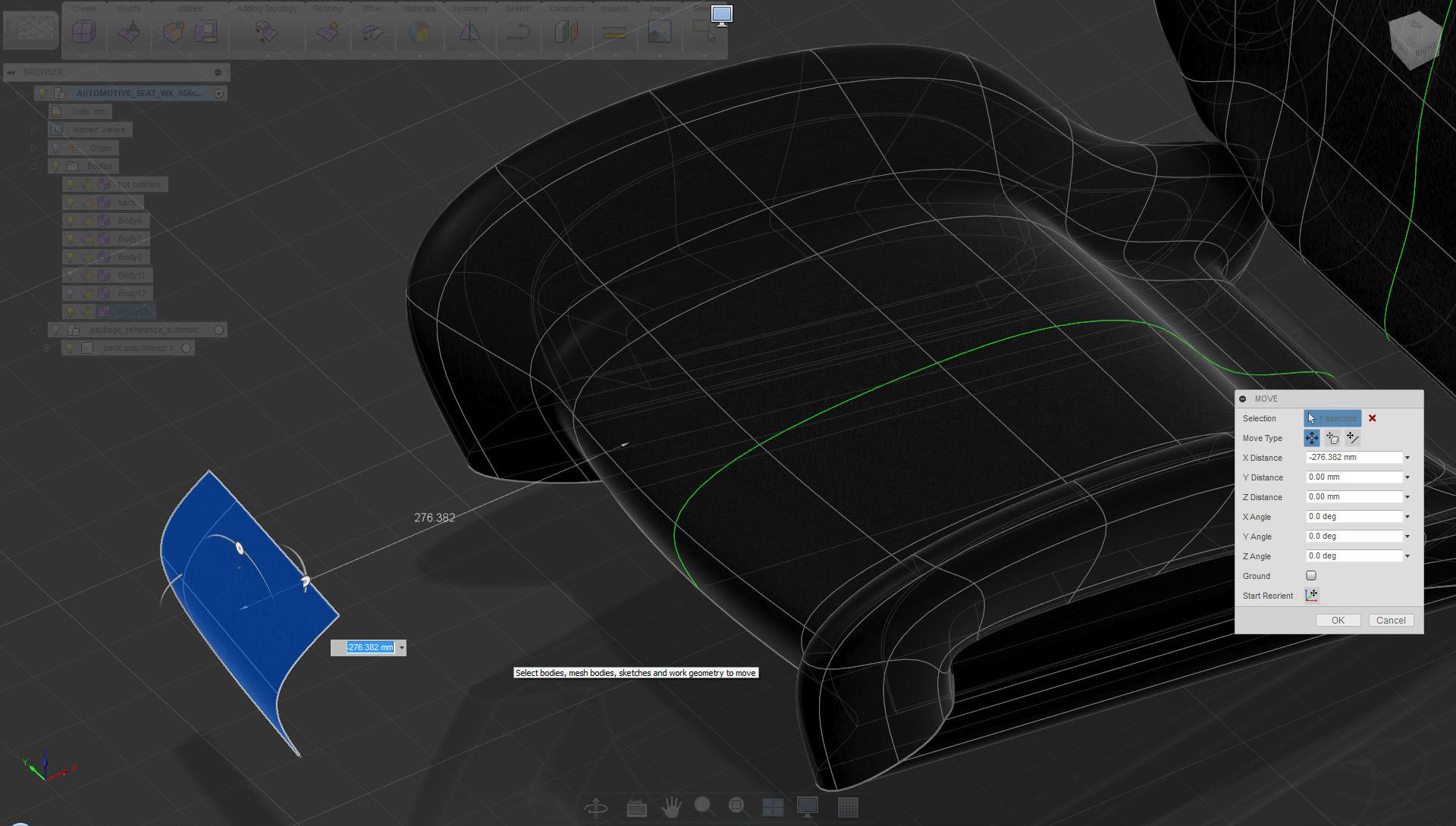
Move newly created surfaces away to gain more working space
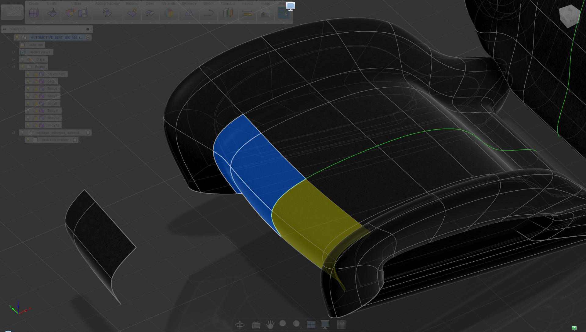
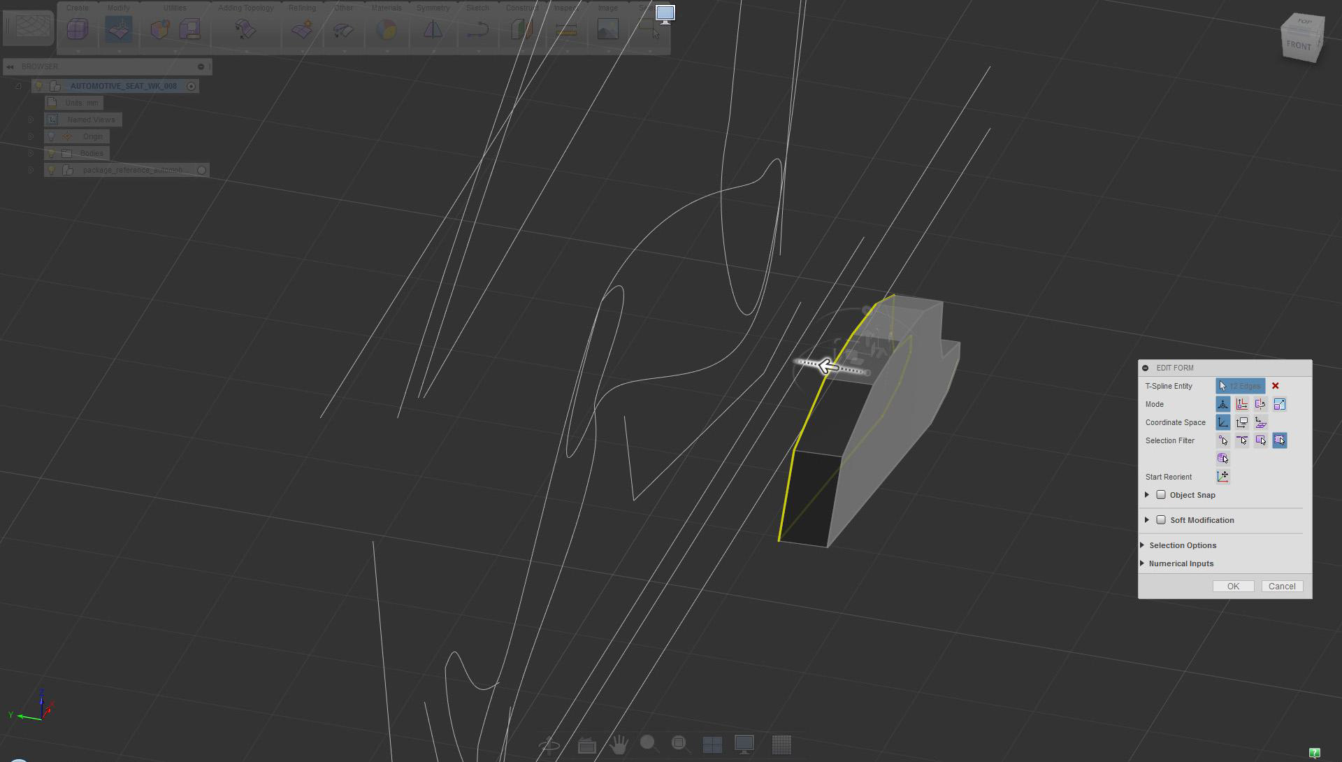
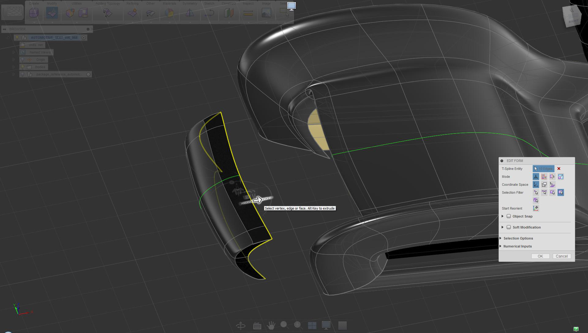
Select surfaces at the front and delete them
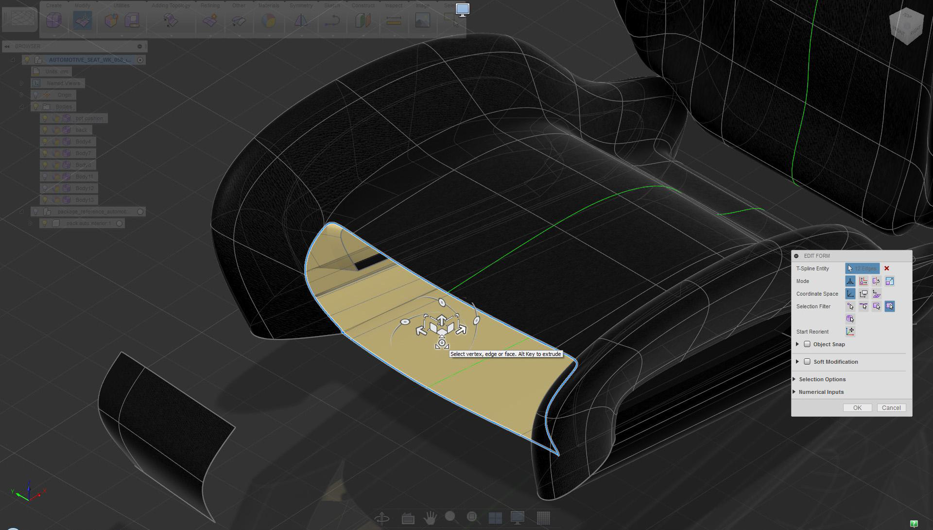
Double-click the edge and use Edit Form extrude, scale mode
Depending on the design, deleting surfaces, and extruding edges may be the best way to build details.
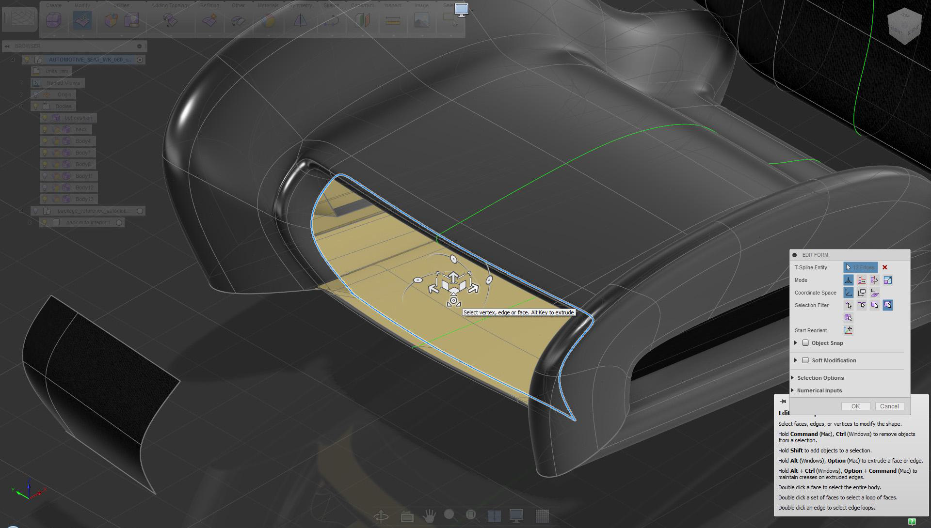
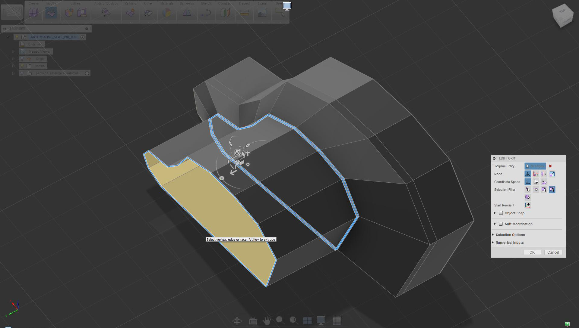
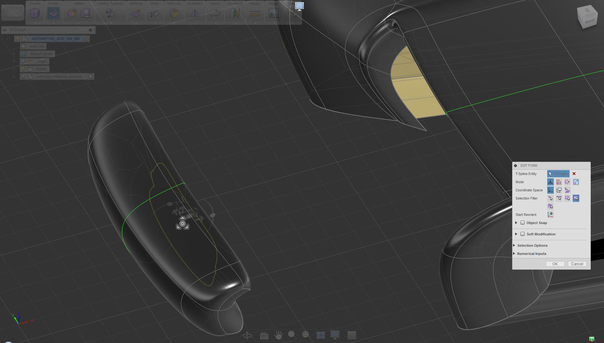
Scale and move while holding Alt to extrude surfaces to create material thickness
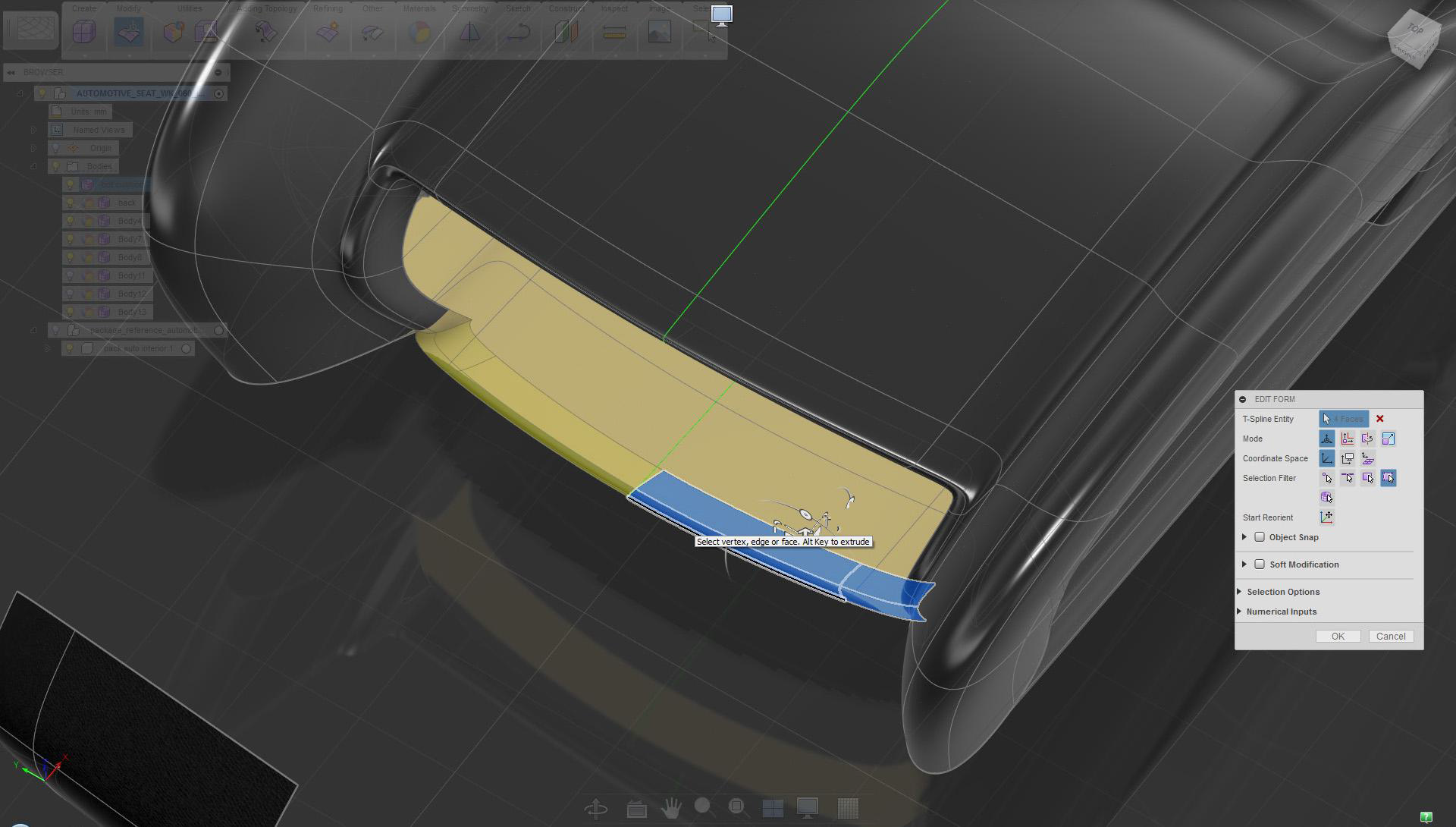
Delete surfaces at the bottom
Mirror Duplicate the surface at the front and move them closer to the seat along the X axis
Extrude edges in along the X axis
Use extrude scale mode on back edges to create back surfaces
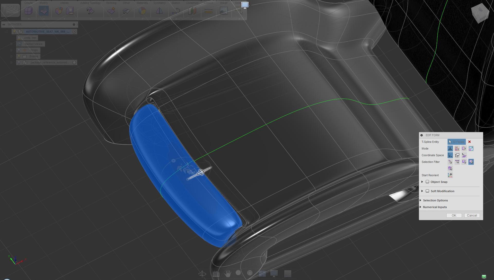
Move the front leg support close to the seat to check the fit
Delete the side faces of the leg support, extrude move the upper edge to extend the surface in the X direction
Move the front leg support cushion in place
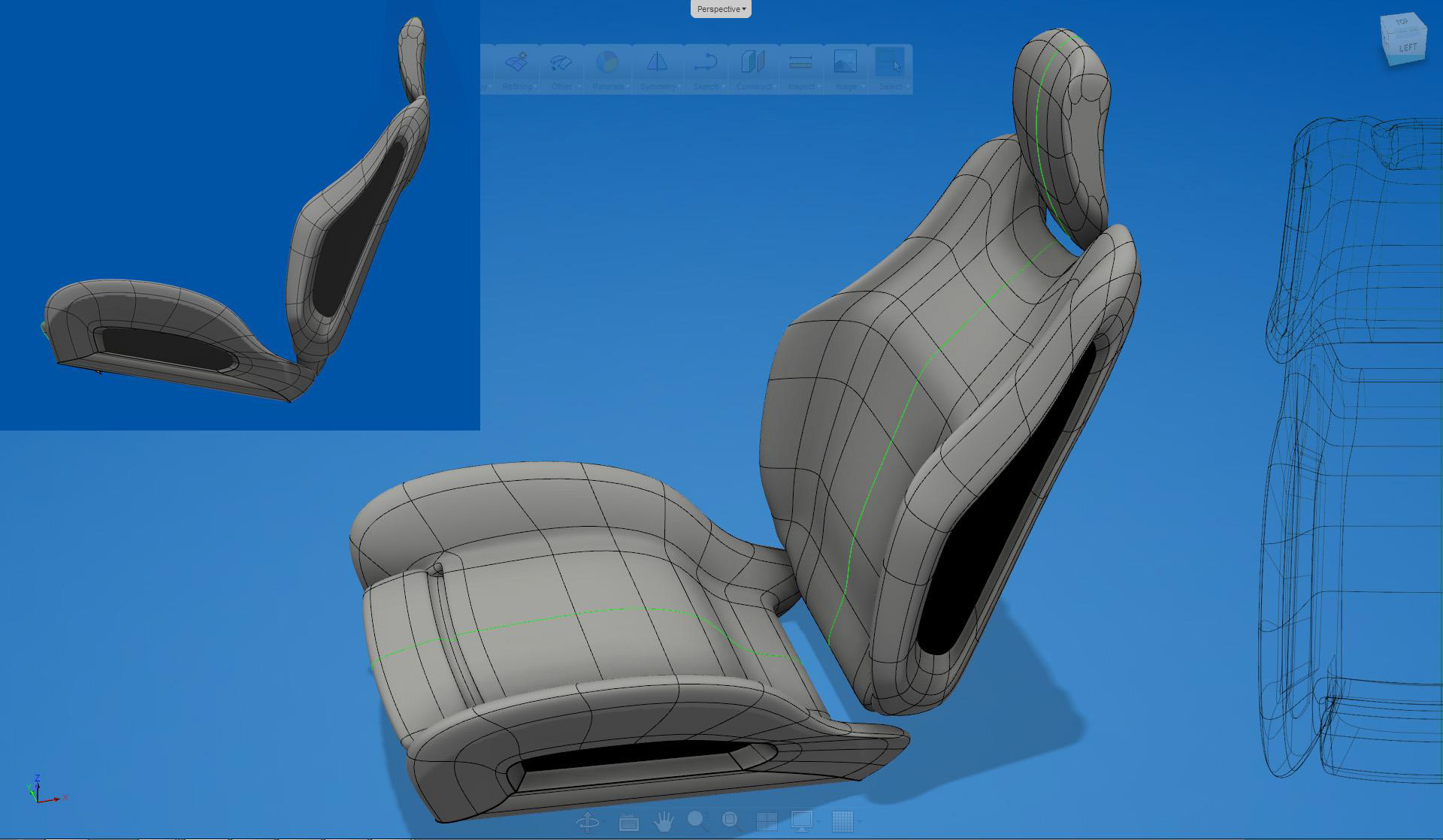
Completed seat model