Autodesk AutoCAD Utility Design 2016 Extension 1
This update contains the following new functionality.
Clearance Check
The AUDCLEARANCE command has been enhanced to support using a rectangular clearance envelop. A new setting "Use rectangular clearance envelop" has been added in Utility Design Options to indicate whether the clearance envelop is rectangular or circular.
Configuration Management
A command AUDCONFIGUPDATE has been added to update a previously created drawing with the latest drawing template configuration. The configuration includes Analysis Option Sets, Custom Data Model, Document properties, Line types, Lookup tables, Model tables, Reports, Rules and Settings. It has 3 modes:
- Auto: Updates the current drawing using the default or saved setting in the source template indicating which data to update and purge.
- Choose: Displays a dialog allowing selection of which settings and purge parameters to update.
- Choose Default: An admin option for defining the default Auto selection of settings and purge parameters for an updated template.
The AUDPURGE command has been enhanced to include more options:
- Purge blocks: Clears all block definitions from the drawing, both 2D and 3D, and redefines the port definitions based on the configured source block drawings.
- Clear temporary preview files: Clears any cached or stale style preview image files from the local temp. This may highly improve the performance of Style Editor.
- Re-apply models: Re-assigns models to all current drawing design features to update them with the latest model definitions.
- Regenerate styles: Forces a recreation of all 2D and 3D objects from their latest styles and style rules.
- Validate all features: Forces validation of all features.
- Resolve all features: Performs auto-resolve during the validation process if the validation option is chosen.
The AUDCONFIGMANAGE command has been enhanced to display the same "Choose" dialog as shown for AUDCONFIGUPDATE to allow for optional inclusion of settings and configuration data.
The command AUDINDUSTRYMODELREMOVE has been added to remove Utility Design industry models from a drawing.
Guying
A new rule point "Is Common Anchor Allowed", under /Analysis/Guying/Equation, evaluates whether the candidate anchor can be used as a common anchor for the new guy.
When a new guy is generated, this rule will be evaluated for all anchors of guys already attached to the pole. If the rule indicates it is allowed to connect to the common anchor, Guying handler will add a resolution "Add new guys with common anchors" and make it default for adding guys, so if auto-resolve is enabled, the common anchor will be used.
Joint Trench
Gas pipes can be added to segments.
Gas pipes can be expanded from segment with the AUDEXPAND command.
Ducts, Conductors, Communication Cables and Gas Pipes can be created without segment.
Layout
The offset distance in the AUDLINEFEATURE command defaults to last value instead of always 5.
The containment relations for line features can be changed on the Feature Info palette.
When a contained line is selected on Feature Info palette, a floating button "Remove this feature from its container" is displayed. When the button is clicked, the feature is uncontained from its container.
The button "Add features to this container" for a line container (e.g. a segment) will now allow selection of features from adjacent sections. Choosing a line will contain it to the selected segment. If the nearest distance from the line to the segment is within the Containment Distance Threshold that configured in Utility Design Options, the line will be shown as a candidate.
Material
Modifying a child material item will invoke the material item rules for itself and its parent material item. This allows authoring of material item rule logic that calculates values for parent items based on child values, such as cumulative totals.
A button "Select filter columns" has been added to the right of the existing Filter checkbox, which allows selection of which properties should be searched. By default it is set to CU and Feature. The selected search properties and filter checkbox state are saved with the drawing. All regular edit operations such as copy/paste, move, etc. should now work when in a filtered view.
Sorting by the Work Location column will sort numerically if the work location name is a valid numeric value. The Work Location edit combo box also displays the values in a numeric sort order.
Some usability enhancements have been made for row selection:
- The row selection column width has been widened to make full row selection easier.
- Row selection has also been enabled via any multi-cell selection operation (such as click-drag) which then triggers full row selection.
- Shift-arrow keys can also be used to trigger full row selection so all right click commands can now be used via keyboard only.
- Right clicking a cell will select the full row and show the context menu.
Pole Head Sizing
Previously only if two conductors with the same model are connected to two dead-end pole heads on the same pole, it allows merging the two pole heads to one double dead-end pole head. Now even if the conductor models are different, as long as they have the same wire count and voltage, you can merge the pole heads.
Pulling Tension
An attribute "Bend Count" of Duct is exposed to indicate the number of bends in the duct.
Two Boolean attributes of "Is Start" and "Is End" of Sweep are exposed to indicate whether the sweep at the start or end of the duct.
Rule
The "Table Lookup" function can be used in aggregate functions.
The Rule is enhanced to support custom feature classes without geometry, which provides the ability to validate and populate their attributes.
A new function "Delete features" has been added in the resolution workflow of "Report and fix" rule to remove features.
Stylization
Pole heads can now be stylized in 2D plan view using 2D symbols, by setting the 2D property "Is Visible" to true in Style Editor.
Voltage Drop
Voltage Drop supports parallel runs of secondary and service conductors.
Customer Total Resistance and Total Reactance properties are now available as separate sum values for use in fault current calculation rules.
The network tracing performed by voltage drop respects the open and close state of devices. An open device (the attribute "State" is "open", "inactive" or "de-energized") won't allow the continuation of a trace.
The Load Devices enumerable property of Transformer Voltage Drop Result and Conductor Voltage Drop Result is exposed in rules, so users can calculate the load factors based on the number of downstream loads. An API attribute "Total Load Count" has also been added in Transformer Voltage Drop Result and Conductor Voltage Drop Result for the same purpose.
Configurations
Some updates have been made to the default templates. Below are for Gas:
- The Sizing rule, Auto Feature Create rule and Connectivity rule of Gas Pipe and Fitting have been updated to better handling block rotations, status, and soft split and hard split.
- The Ribbon tab for Gas has been enhanced to fit with the content changes.
- The style blocks for Elbow and Tee have been updated to add wipeout masking. The variable WIPEOUTFRAME is set to 0 in the default drawing template "TemplateSpec-MU.dwt" to make them visible.
- Service Tee has been replaced with Service Saddle in models and styles.
- The feature class "House Connector" now has a model table. The styles and models of Service Riser in Fitting have been moved to House Connector. A house connector will be created at the end of a service pipe.
And one for Electric:
- The filter "Is Double = true" has been added to the anchor sizing rule to size common anchor, and a general validation rule for the anchor to restrict to max of 2 connected guys.
Autodesk AutoCAD Utility Design 2016
The Utility Design 2016 release contains the following enhancements:
Soft Split and Hard Split
- This release introduces a new concept of "Soft Split". The purpose is to allow the attachment of a point feature (branching saddle, tee or other fitting) without breaking the total length of pipe into individual pieces separated by fitting while maintaining connectivity.
- Soft split is only supported in the Gas industry model, not the Structural, Electric or Communication industry models.
- Gas pipes can be soft split by a gas device. If a gas pipe is soft split, it will still be editable as a single polyline object and share the same attribute information for all sub-segments. If a gas pipe is hard split by a device, it will be split into completely separate gas pipe features with editable polyline objects.
- Viewing connectivity for a gas pipe will show all devices connected to the overall gas pipe feature, including both hard and soft split devices. However, internally the detailed topology and connectivity between each gas pipe sub-segment and device is defined and maintained automatically.
- Disconnecting a soft split gas device will remove the soft split from the gas pipe and merge the underlying sub-segments.
- "Total Length" attribute of line Feature Classes (e.g. Gas Pipe), shows the total length of all the contained polylines.
- You can modify a soft split line with the AutoCAD commands Move, Stretch, Grip, Rotate, Vertex, Copy, Cut, Paste, Break, Explode, etc.
Connectivity Rule
- A new rule type "Connectivity" is added which allows user configurable logic for determining allowed connectivity, disallowed connectivity, soft split, hard split, disallowed merging and disallowed tapping behaviors.
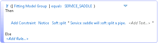
For example, with the following connectivity rule for Fitting, placing a service saddle onto a gas pipe will soft split the pipe.
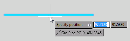
- The dynamic connectivity tooltip will apply the connectivity constrains defined in the Connectivity rule.
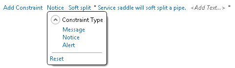
- With a connectivity rule with constraint type "Message" or "Notice" applied, the resultant connectivity tooltip will default to the defined constraint but allow the user to change it; while with "Alert" the user won't be allowed to change it.
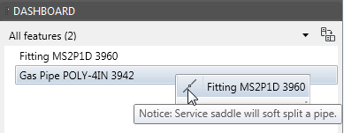
- The Feature Info is also enhanced to support the connectivity rules. The message defined in rule will show when hovering the mouse over the icon.
Auto Create Feature Rule
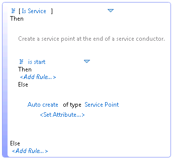
- A new rule type "Auto Feature Create" is added which allows user configurable logic for creating features when draw a line to connect or tap another line, or at the end of lines.
For example, with the following auto feature create rule for Conductor, a service point will be added at the end when draw a service conductor.
One Line and One Line Rule
- A ribbon menu "Insert One Line" with command AUDONELINE is added to create a circuit one line schematic diagram in either model or paper space. The user can specify the scale of the one line diagram in the command. Note that only lines will be scaled, but not blocks and annotations.
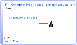
- A new rule type "One Line" is added to: 1. determine which features will be added in the one line diagram; 2. define the styles for line and point features in the one line diagram. The styles are defined in the Industry Model Configuration, which are the same as the ones used in the Style rule.
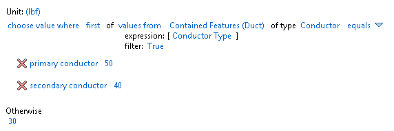
For example, with the following one line rule for Conductor, only primary conductors will be shown in the one line diagram with the "one line" style, while secondary and service conductors will not be shown.
- A Subrule defined in the Style rule point can be used in the One Line rule of the same Feature Class, and vice versa.
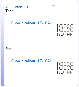
- To add annotations in the one line diagram, the annotation rule needs to be defined using the "is one-line" function. For example, the "If... Then..." below defines the annotation for the one line diagram, while the "Else…" defines the annotation for the main design. They can be the same or different.
Surface and Profile
- This release introduces the ability to easily create a civil surface. The purpose is to allow the creation of a surface from points and lines that will be recognized by Utility Design when inserting features.
- A Ribbon menu "Create Surface" with command AUDSURFACE is added to create a civil surface from points, lines, etc. The command MAPIMPORT can be used for generating point entities from survey or GPS point data.
- The Ribbon button "Create Profile" with command AUDPROFILE will create a civil profile for overhead designs.
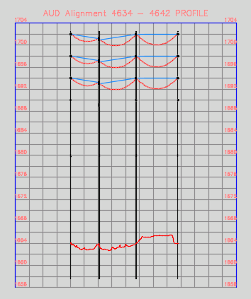
- To use the surface and profile commands, the drawing file must have Civil 3D settings defined. Such a drawing file can be created by either using the INSERT command to insert a Civil template into a Utility Design drawing or by opening a Civil template and importing a Utility Design industry model with the AUDINDUSTRYMODELADD command.
- The styles and settings of the profile and alignment are configurable. The user should first configure them in the template using Civil 3D, and then define which to use for the created surfaces, alignments, profiles and profile views in Utility Design Options/Civil.
Replace Workflow
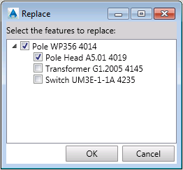
- A Ribbon menu "Replace and Transfer" with command AUDREPLACE is added to transfer devices and equipment from a removed structure (like a pole) to a new structure. The purpose is to steamline the workflow required to replace specific existing features while transferring others as a single process.
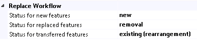
- The status values used in the "Replace and Transfer" workflow for the new, replaced and transferred features can be configured in Utility Design Options/General Layout/Replace Workflow.
Project Explorer
- Two new buttons, "Expand all items" and "Collapse all items" are added on the Project Explorer palette. They are used to expand or collapse all the projects, work orders and design drawing on the tree view.
- Short keys are added, including ENTER key to open a drawing, DEL key to delete a drawing and F2 to rename a drawing.
Data Exchange
- This release supports adding merge back expressions for industry model data sources on the Mapping Configurations dialog.

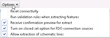
- An option "Allow extraction of schematic lines" has been added to the Mapping Configurations dialog. If enabled, it will copy the schematic geometry from GIS when imported into Utility Design, and will also merge back the schematic geometry to GIS.
Layout
- An option "Schematic Arcs for Connectivity" has been added to "Utility Design Options/General Layout/Layout" to indicate whether to generate semi-circular arcs around point features for expanded schematic lines when the line and the point are not connected.
- When using AUDEXPAND to expand a line, if the user picks the offset distance with the graphical option the system will determine the offset direction based on the picked point.
- In Geometric Proximity mode, placing a device will tap the conductor at the segment endpoint if it's within the defined "Automatic Connection Tolerance" distance.
Validate and Resolve
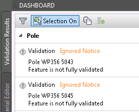
- You can now cancel the auto-resolve process by pressing ESC (escape) key. If the process is cancelled or validation is disabled, all of the features that are not validated will have ignored notices on Validation Results palette (if "Ignored Notices" is set to show).
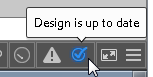
The status bar displays an icon indicating the status of validation. If validation is disabled or cancelled, the icon will indicate the drawing needs to be updated.
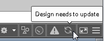
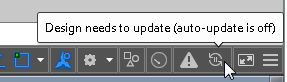
Click the status bar icon to complete all validation, or alternatively the features requiring validation can be selected and the "Resolve Selected" button used to finish the process.
- An option "Validation Delay" is added to "Utility Design Options/General Layout/Layout", to specify the number of seconds to delay before running validation when auto validation is enabled. If the value is set to zero, validation will run immediately upon changes to the design.
Pulling Tension
- Two new equation rule points "Vertical Entrance Length" and "Vertical Exit Length" have been added for Pulling Tension.
"Vertical Entrance Length" determines the length of the vertical section (usually the connected riser) at the feed point. Pulling tension will calculate a slope downhill section with this length and 90-degree angle at the feed point.
"Vertical Exit Length" determines the length of the vertical section at the pull point. Pulling tension will calculate a slope uphill section with this length and 90-degree angle at the pull point.
- The "Reel Tension" option has been moved from "Option Set" to an equation rule point, which determines the reel tension as the conductor/cable enters the first section in the path. Moving "Reel Tension" to Rules also allows different values to be set for different cabled depending on the rules written.
For example, the reel tension in the rule below is based on different conductor types.
Pole Leveling
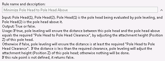
- 8 new rule points are added for pole leveling under "Analysis/Pole Attachments/Minimize Clearance".
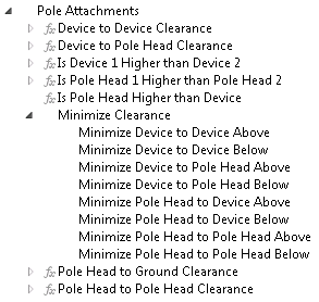
With these rule points, user can determine whether to minimize the clearance from the evaluated attachment to the attachment above or below it. Descriptions for each of these rule points has been added as a reference on how use the rule:
Clearance Check
- The 5 clearance check functions all return document unit, and the unit is displayed with the function.
- minimum ground clearance
- closest points clearance
- minimum horizontal clearance
- minimum vertical clearance
- minimum vertical clearance where horizontal violated
Material
- You can define expression Subrules for Material Item, for example under "Expressions/Boolean/Material Items", and the Subrules can be used in "Material/Material Item rule".
- An option "Always rest material" is added on the Summation tab of Material List Configuration dialog. If enabled, every change in to a feature in the design will trigger the re-ordering of its materials; otherwise if disabled, the edited materials won't be reset even if the feature is changed, unless its Model Name or Status is changed.
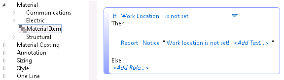
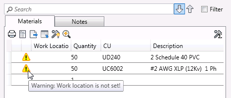
- Validation messages from "Material/Material Item" rule are shown on Material Editor. For example, with the validation rule below, a material item without work location will have a warning icon with tooltip before it.
3D Visualization
- When switching from 2D to 3D, the view scale will be kept so that it's easier to find the area that was being edited in 2D, especially when there is base map added. The same enhancement has also been done for switching from 3D to 2D.
3D Underground
- On the "Transition Points" palette, the column "Projection Length" is renamed to "Projection Length 2D", and meanwhile 3 new columns are added, "Reversed Projection Length 2D", "Projection Length 3D", and "Reversed Projection Length 3D".
- With these columns the user is able is to edit transition points either based on 2D or 3D projection length. And once one of the projection lengths is changed, the others will be updated automatically.
- The "Reversed Projection Length 2D" and "Reversed Projection Length 3D" allow the user to add transition points based on the reversed projection length, i.e. the projection length from the end point.
Rule
- The "Set attribute" function has been enhanced so that the feature won't be updated if the attribute is already the expected value.
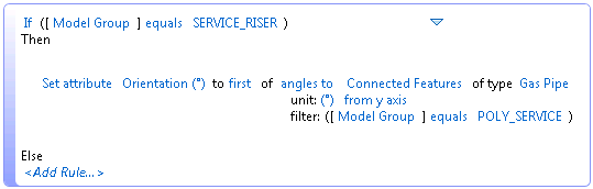
- A new rule function "angles to features" has been added for use with the aggregate functions. This can be used for setting the default rotation of a point feature to be aligned with its connected line features. Point to point is also supported.
For example the rule below will set the rotation of a service riser to be aligned with the connected gas service pipe.
Performance
- A new option "Generate 3D Objects" is added in Utility Design Options/General Layout/Replace Workflow. If it's set to "True", 3D objects are always generated; otherwise if false, 3D objects are not generated, so layout in 2D will be faster. Changing this option from false to true will trigger the regeneration of 3D objects.
- The performance is improved for layout and editing in 3D view.
Configurations
- The support for gas design is now included. A new template "AUD US - MultiUtility.dwt" has been added. This template includes sample blocks and styles, validation rules, sizing rules and connectivity rules for Gas.
- A new tab "Gas" is added to the Ribbon with menus for drawing gas pipes and placing gas devices. The menus can be used only if a DWT or DWG contains the Gas industry model, for example the "AUD US - MultiUtility.dwt" template.