Refer to the Beam Tower drawing below for the orientation of the angles and the beam endpoint coordinates.
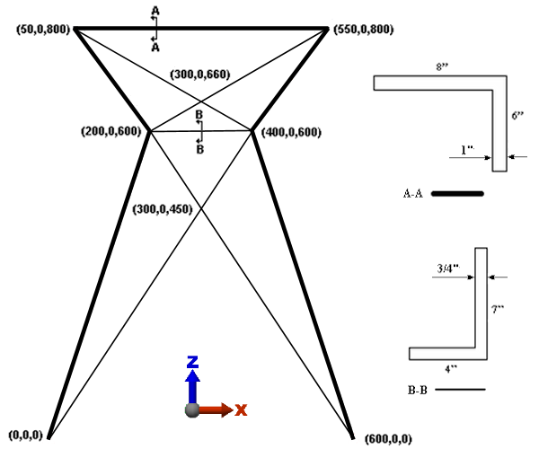
First, we draw the beam elements that represent the 8x6 angle. To use the AISC library to assign the cross sectional properties, the local 2 axis must be parallel to the weak axis of bending. The weak axis is parallel to the longer leg of the angle cross-section. Therefore, for the 8x6 angles, the weak axis is parallel to the global Y axis. Since the long leg of the angle is pointing in the -Y direction, as shown by the orientation of Section A-A, we need to specify a beam orientation specifically in the -Y direction. In Simulation Mechanical, beams on Surface 4 are assigned a local 2 axis orientation in the -Y direction (refer to the Beam Elements page of the Help).
- Click
 View
View Navigate Orientation Front View. We are drawing lines in the XZ plane.
 - Select
 Draw Draw Line. Then...
 - Clear the Use as Construction check box. To be recognized as beam elements, we must draw actual lines, not construction objects.
- Type 4 in the Surface: field.
- Press Enter to define the origin as the first point.
- To specify the next point (200,0,600), type 200 in the X: field, press Tab twice, type 600 in the Z: field, and press Enter.
- Type 50 in the X: field, press Tab twice, type 800 in the Z: field, and press Enter.
- Type 550 in the X: field, press Tab twice, type 800 in the Z: field, and press Enter.
- Type 400 in the X: field, press Tab twice, type 600 in the Z: field, and press Enter.
- Type 600 in the X: field and press Enter.
Attention: Do not terminate the Line command. We will add more line segments in the next page. - Select
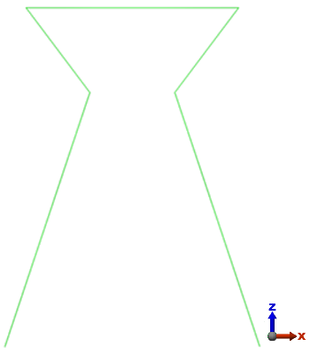
 View Navigate Enclose.
 The model should display as shown in the following image.
Select Lines command, choose the lines to change, right-click in the display area, and choose the Edit Attributes command.