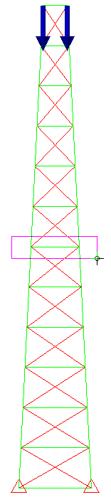
Now we apply the four 175 lbf forces in the -X direction to the center of the model.
- Click and drag to draw a box enclosing the center of the model as shown in the following image.
- Click Setup
 Loads Force.
 - Type -87.5 in the Magnitude field
- Select the X radio button. Again, we have cut the force in half because there are two nodes at each vertex, one per part.
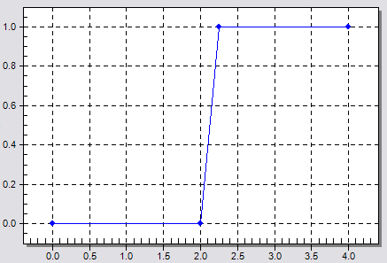
- Type 2 in the Load Case / Load Curve field and click Curve. The Multiplier Table Editor dialog box displays for defining a load curve.
- Click Add Row three times so that there is a total of four rows in the table.
- Type 2 in the second row of the Time column.
- Type 2.25 in the third row of the Time column
- Type 1 in the third row of the Multiplier column.
- Type 4 in the fourth row of the Time column.
- Type 1 in the fourth row of the Multiplier column.
- Press Enter. The load curve should appear within the dialog as shown below.
- Click OK to accept the load curve.
- Click Add Row three times so that there is a total of four rows in the table.
- Click OK to apply the forces.