To have the results calculated at more data points, we need to divide each of the existing lines into multiple segments. Ten elements per beam member is sufficient. Stresses and displacements are only calculated at the beam element endpoints.
- With the
 Selection
 Select Lines command active, press Ctrl-A, to select every line within the model.
 - Click
 Draw Modify Divide. Note that you can also access the Divide command from a context menu by right-clicking in the display area.
 - Type 10 in the Number of Lines field.
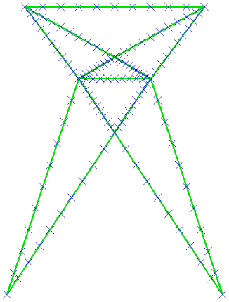
- Click OK. The model appears as shown below. Note how the display of endpoints provides visual confirmation that the original beam elements have all been divided.
- Deactivate the
 View Visibility Endpoint Vertices option. The model appears as shown below.
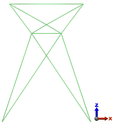
- Click
 Save on the Quick Access Toolbar (QAT) to save your model.
This tutorial is now complete. You can use this model to complete the Beam Tower Static Stress Analysis tutorial.