Next, apply the constraint to the bottom surface of the computer case.
- Of the ViewCube, click near the middle of the edge where the Front and Top faces meet. This will produce an oblique view of the model (rotated half-way between the Front and Top views), as shown below.
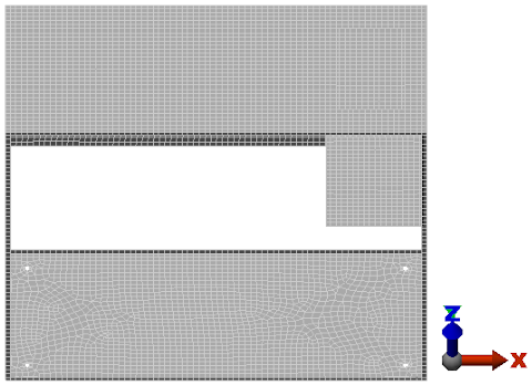 Tip: Clickable zones on the ViewCube (which includes faces, edges, and corners) will turn light blue when the cursor is over them. Clicking edges produces various oblique views and clicking corners produces various isometric views.Note: The view shown above provides good visibility of the holes in the bottom surface. The holes would be harder to see in a Bottom view because of the other gray surfaces that would be in the background from that viewpoint. Here, we see only white background beyond the holes.
 - With the
 Selection
 Shape Point or Rectangle and
  Selection Select Edges commands active, click and drag to draw a selection rectangle that encloses the four holes in the bottom of the case, as shown below.
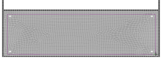
All four holes should now have magenta edges, indicating that these edges are selected.
- Click
 Setup Constraints General Constraint.
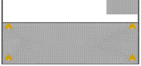
 - Click Fixed
- Click OK. The fixed constraint glyphs appear as shown below.
- Click the
 Home icon above the ViewCube to return to an isometric view.