- Click
 Mesh
Mesh  CAD Additions Bolt. The Bolted Mesh Setup dialog box displays. Note: Activating this command automatically places the program in the Select Surfaces mode. However, the model remains colored according to the part numbers, not the surface numbers. To color the model according to the surface numbers, you can use
 View Appearance Color By Surface. Images in this tutorial are based on the default Color by Part option.
 - Type 0.5 in the Bolt diameter field.
- Type 6 in the Number of spokes field.
- Click
 View Navigate Orientation Front View.
 - With the
 Selection Shape Point or Rectangle command active, click the surface of the flange facing the screen, as shown pre-highlighted in yellow in the image below.
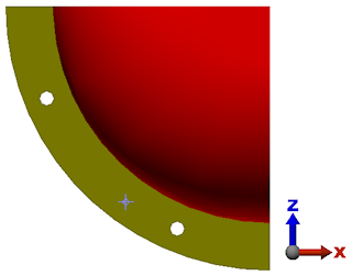
- Click the Add button to the right of the Contact surface(s) box in the Bolt head section.
- Type 0.85 in the Head diameter field.
- Click
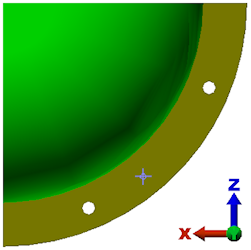
 View Navigate Orientation Back View.
 - Click the surface of the flange now facing the screen, as shown pre-highlighted in yellow in the image below.
- Click the Add button to the right of the Contact surface(s) box in the Nut section.
- Type 0.85 in the Nut diameter field.
- Click, drag, and release the left mouse button to draw a selection rectangle enclosing the hole near the bottom of the display.
- Click Add in the Interior hole surfaces for one hole section.
- Type 30 in the Axial Force Magnitude field.
- Activate the Do not dismiss dialog after bolt generation check box. We will create a second bolt using identical parameters, except for the interior hole surfaces. Checking this box keeps the dialog box open and retains all needed parameters so that the second bolt can be more easily created.
- Click OK. The first bolt appears as shown below. The bolt (Part 3) has been selected for better visibility.
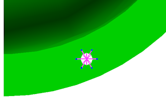
- Click OK. The first bolt appears as shown below. The bolt (Part 3) has been selected for better visibility.