- Click
 Mesh
Mesh Mesh 3D Mesh Settings.
 - Click the Options button.
- Select Absolute mesh size from the Type drop-down list.
- Type 0.15 in the Size input field.
- Click OK.
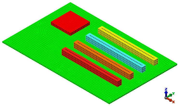
- Click Mesh model. The meshing process starts. If asked to review the mesh results, click No. The meshed model displays as shown in the following image.
- Click the Options button.
- Use the
 View Navigate Orbit Orbit,
  View Navigate Zoom Zoom, and
  View Navigate Pan commands (or the related ViewCube or Navigation Bar tools) to inspect the mesh in various areas of the model.
Note: Even though the default mesh type is Solid, only the surface mesh has been created at this point. By default, the generation of the interior mesh lines is postponed until the first time the Run Simulation or Check Model command is executed.
This tutorial is now complete. Use the meshed model to complete the Circuit Board Steady-State Heat Transfer Analysis tutorial.