Now that the element type, definition, and material are defined, we can check the model, which will validate it and render it in the Results environment. Before applying constraints and loads, check the model to see how the beams appear when visualized in 3D.
- Click
 Analysis
  Analysis Check Model. The model is validated and then displayed within the Results environment. 3D visualization of beam elements is enabled by default.
 - Click
 View Appearance Visual Style Shaded with Mesh. This makes the beam orientation easier to see.
 - Use the mouse wheel to zoom in (rotate the wheel), to rotate the viewpoint (click the middle button and drag the mouse), and/or to pan the view (hold Ctrl while dragging the mouse with the middle button clicked). Carefully examine the orientation of the beams. The description below summarizes what you should see if the beams were drawn exactly as described in the Beam Tower Model tutorial.
- The long leg of all of the 8x6 angles is pointing in the -Y direction, as it should be.
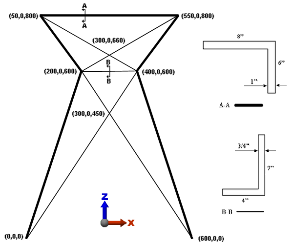
- The short leg of the top, horizontal 8x6 angle is pointing downward, which is consistent with Section A-A in the tower drawing.
- The short legs of the 8x6 angles all point inward (that is, towards the interior of the tower outline). This arrangement is consistent with the top, horizontal member and provides for good 3D visualization of the beam member connections at each corner.
- The long legs of all of the 7x4 angles are in the XZ plane and pointing upward, as shown in Section B-B of the beam tower drawing above.
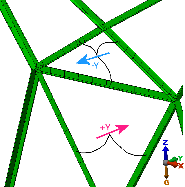
- The short legs of the 7x4 angles point in inconsistent directions. This leg, for the short horizontal member and the diagonals above it, points in the -Y direction, which is consistent with Section B-B of the drawing above. However, for the diagonals below the short horizontal member, the short leg points in the +Y direction. The image below shows this discrepancy.
Note: The direction of the short leg of the angles corresponds to the local 3 axis of the beam elements. All of the element properties in this model are correctly oriented in order for the calculated stresses and displacements to be correct. The properties are identical whether bending in the plus or minus direction about each local axis. However, solely for the purpose of 3D visualization, it is desirable to have all beams facing the same direction. Of course, for symmetrical beams (such as rectangles and wide flange beams), the appearance is identical when the beam is turned around (from the plus to minus direction, that is).
On the next page, we show you how to turn the lower diagonal 7x4 beams around for consistent 3D visualization.