Check and design the behavior of composite steel beams according to the ANSI/AISC 360-10 code.
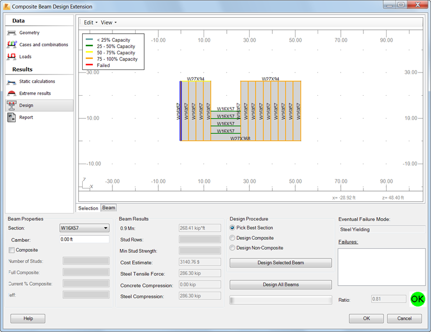
Using the Design tab you can specify design settings:
- Section
To check the beam behavior, you can select different sections from the Section list. They are verified instantly. If a section does not fulfill the ANSI/AISC 360-10 design requirements, the
 icon displays. The Failures field shows the information why the beam parameters are incorrect. Select a section again until the
  icon displays.
 - Camber
The Camber field is active if you select Design beam with camber in the Composite Settings dialog, on the Deflections and Camber tab. You can modify the camber value within the range of camber settings specified on this tab.
- Composite
Select this setting to design a beam as composite. However, it is possible only if positive moments occur in the beam. If negative moments occur, the composite option is inactive. This setting is selected automatically, if you select the Design Composite procedure. If you select the Design Non-Composite procedure, Composite is automatically deselected.
- Number of Studs
The Number of Studs field is active if you select Composite. By default, it displays the minimum required number of studs for the selected beam. You can increase this value.
In addition, there are 2 read-only stud settings:
- Full Composite. The number of studs required to achieve full composite action between the beam and the slab.
- Current % Composite. Shows the percentage of composite action achieved with the current stud number.
- Design procedures. They select the optimal section.
- Pick Best Section. Depending on the beam behavior, it uses one of the remaining procedures: Design Composite or Design Non-Composite. See Design Assumptions.
- Design Composite. It treats the section as a T-beam (steel beam composed with an RC slab). You can use this procedure for beams that can be designed as composite. See Design Assumptions.
- Design Non-Composite. It treats the section as a steel beam section only. The RC slab is not included in the calculations.
- Design options. To start design, click on of the following:
- Design Selected Beam. It automatically selects the optimum section, number of studs, and camber for the beam selected in the graphic viewer.
- Design All Beams. It automatically selects the optimum section, number of studs, and camber for all selected beams based on the internal forces resulting from the method of calculating forces you selected.
Design results include:
- Uniform studs distribution
- Segmented studs distribution
- Designed section
- Moment capacity
- Maximum moment
- Stud rows
- Stud strength
- Steel tensile force
- Cost estimate
- Compressive force in concrete
- Compressive force in steel
- Failures
- Ratio.
In addition, the graphic viewer presents studs designed on the beam.
After design is finished, click OK to update the Robot model with changes in section, number of studs, and camber, and close the extension.
After updating the model, in Robot perform static calculations. Then repeat the design in Rozszerzenie Projekt belki kompozytowej using updated results of static calculations.