This subassembly creates a simple lane with finish surface and subbase, where the edge of carriageway can be tied to an alignment or profile.
Attachment
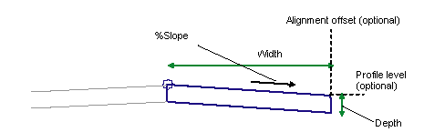
The attachment point is either (a) at the inside edge of lane on finished gradient, if the insertion point is Crown, or (b) at the outside edge of travel way, if the insertion point is at the edge of travel way.
Input Parameters
Note: All dimensions are in meters or feet unless otherwise noted. All slopes are in run-over-rise form (for example, 4 : 1) unless indicated as a percent slope with a “%” sign.
|
Parameter |
Description |
Type |
Default |
|---|---|---|---|
|
Side |
Specifies which side to place the subassembly |
Left / Right |
Right |
|
Insertion Point |
Specifies insertion point of the lane either at the crown, or at the edge of travel way |
List of options: Crown, Edge of Travel Way |
Crown |
|
Crown Point on Inside |
Specifies that the inside edge of travel way be coded as Crown |
Yes / No |
Yes |
|
Width |
Width of lane |
Numeric, positive |
3.6 m 12.0 ft |
|
Depth |
Depth from finish surface to subbase |
Numeric, positive |
0.2 m 0.67 ft |
|
%Slope |
% Slope of the lane |
Numeric |
-2% |
|
Transition |
Describes how the subassembly behaves when an alignment, profile, or both are used as target parameters. Choices are provided in a list including: Hold offset and level Hold level, change offset Hold gradient, change offset Hold offset, change level Change offset and level |
Menu |
Hold offset and level |
Target Parameters
This section lists the parameters in this subassembly that can be mapped to one or more target objects. For more information, see in the AutoCAD Civil 3D User’s Guide Help.
|
Parameter |
Description |
Status |
|---|---|---|
|
Edge Offset |
May be used to override the fixed Width value and tie the edge of carriageway to an offset. The following object types can be used as targets for specifying the offset: alignments, polylines, feature lines, or survey figures. |
Optional |
|
Edge Level |
May be used to override the fixed slope and tie the edge of carriageway to a level. The following object types can be used as targets for specifying the level: profiles, 3D polylines, feature lines, or survey figures. |
Optional |
Output Parameters
None.
Behavior
This subassembly provides a simple travel lane that can tie to an alignment for variable width, and a profile for variable slope. The behavior depends on the Transition type selected:
|
Transition Type |
Description |
|---|---|
|
Hold offset and level |
The width and slope of the lane is held to the Width and % Slope input parameter values. |
|
Hold level, change offset |
The level of the edge of carriageway is calculated from the Width and % slope input parameter values. The width is then tied to the offset alignment. |
|
Hold gradient, change offset |
The width is adjusted to tie to the offset alignment. The % Slope input value is held for the adjusted width. |
|
Hold offset, change level |
The width is held to the Width input parameter value. The level of the edge of carriageway is tied to the offset profile. |
|
Change offset and level |
The width is tied to the offset alignment, and the slope is adjusted to tie the level of the edge of carriageway to the offset profile. |
Layout Mode Operation
In layout mode, this subassembly draws the lane using the input parameters.
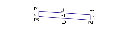
Point, Link, and Shape Codes
The following table lists the point, link, and shape codes for this subassembly that have codes assigned to them. Point, link, or shape codes for this subassembly that do not have codes assigned are not included in this table.
|
Point, Link, or Shape |
Codes |
Description |
|---|---|---|
|
P1 |
Crown |
Crown of road on finish surface |
|
P2 |
EC |
Edge of carriageway on finish surface |
|
P3 |
Crown_Subbase |
Crown of road on subbase |
|
P4 |
EC_Subbase |
Edge of carriageway on subbase |
|
L1 |
Top, Pave |
Paved finish surface |
|
L3 |
Datum, SubBase |
Subbase |
|
S1 |
Pave1 |
Coding Diagram