This subassembly creates a cross-sectional representation of a depressed central reserve with inside shoulders, using vertical termination of shoulder subbase.
It supports superelevation pivoting about the attachment point at the centerline, or about the attachment point level at the inside edges of carriageway. The pavement structure on the paved portions of the shoulder follows the standards described in "Pavement Structure of Paved Sections" in the AutoCAD Civil 3DHelp.
| Table of Widths | Table of Slopes | ||
|---|---|---|---|
|
W1 |
Ditch |
S1 |
Ditch of Foreslope |
|
W2 |
Left Central Reserve |
S2 |
Unpaved Shoulder Slope |
|
W3 |
Right Central Reserve |
S3 |
Left Inside Superelevation |
|
W4 |
Paved Shoulder |
S4 |
Right Inside Superelevation Shoulder Slope |
|
W5 |
Unpaved Shoulder |
S5 |
Left Outside Lane Slope |
|
W6 |
Left Turning Lane |
S6 |
Right Outside Lane Slope |
|
W7 |
Right Turning Lane |
||
Attachment
The attachment point is above the centerline of the ditch. The location of the central reserve links relative to the attachment point varies depending on the pivot method, and in some cases, the central reserve widths and lane slopes. The attachment point is typically placed on the baseline alignment at the design profile level.
Input Parameters
Note: All dimensions are in meters or feet unless otherwise noted. All slopes are in run-over-rise form (for example, 4 : 1) unless indicated as a percent slope with a “%” sign.
|
Parameter |
Description |
Type |
Default |
|---|---|---|---|
|
Ditch Width |
Width of the bottom of the central reserve ditch (zero for a V-ditch |
Numeric, positive |
0.6 m 2 ft |
|
Ditch Slope |
Inward slope from the shoulders toward the bottom of ditch (x : 1) |
Numeric, positive |
4 : 1 |
|
Hold Ditch Slopes |
For the cases where the top-of-ditch-slope points are at unequal levels, selects whether to hold the ditch sideslopes and let the position of the ditch shift, or to hold the ditch at the center and adjust the sideslope on the high side. |
Selection list |
Hold ditch sideslopes, shift ditch from center |
|
Centerline Pivot? |
Select whether the profile gradient and pivot point is at the centerline above the central reserve ditch, or if it is held at the inside edges of carriageways |
Selection list |
Pivot about inside edge of carriageway |
| Shoulder Slope Direction | Specifies whether the shoulder slopes away from the crown or towards the crown |
Selection List:
|
Away from Crown |
|
Left Central Reserve Width |
Width from the central reserve centerline to the left inside edge of carriageway |
Numeric, positive |
6.6 m 22 ft |
|
Right Central Reserve Width |
Width from the central reserve centerline to the right inside edge of carriageway |
Numeric, positive |
6.6 m 22 ft |
|
Paved Shoulder Width |
Width of the paved portion of the inside shoulder |
Numeric, positive |
0.6 m 2.0 ft |
|
Unpaved Shoulder Width |
Width of the unpaved portion of the inside shoulder |
Numeric, positive |
1.2 m 4.0 ft |
|
Unpaved Shoulder %Slope |
% slope of the unpaved portion of the inside shoulder |
Numeric |
-6 (%) |
|
Pave1 Depth |
Depth between the finish surface and Pave1 surface |
Numeric, positive |
0.025 m 0.083 ft |
|
Pave2 Depth |
Depth between the Pave1 and Pave2 surfaces |
Numeric, positive |
0.025 m 0.083 ft |
|
Base Depth |
Depth between the Pave2 and Base surfaces |
Numeric, positive |
0.100 m 0.333 ft |
|
Subbase Depth |
Depth between the paved shoulders’ finish surface and subbase surfaces |
Numeric, positive |
0.3 m 1 ft |
|
Left Turning Lane Width |
Width of the optional turning lane on the left side |
Numeric, positive |
0 |
|
Right Turning Lane Width |
Width of the optional turning lane on the right side |
Numeric, positive |
0 |
Target Parameters
This section lists the parameters in this subassembly that can be mapped to one or more target objects, such as a surface, alignment, or profile object in a drawing.
|
Parameter |
Description |
Status |
|---|---|---|
|
Ditch Slope |
May be used to override the Ditch Slope and tie the central reserve bottom-of-ditch to a profile. The following object types can be used as targets for specifying this: profiles, 3D polylines, feature lines, or survey figures. |
Optional |
|
Left Central Reserve Width |
May be used to override the fixed Left Central Reserve Width and tie the left inside edge of carriageway to an offset alignment. The following object types can be used as targets for specifying this offset: alignments, polylines, feature lines, or survey figures. |
Optional |
|
Right Central Reserve Width |
May be used to override the fixed Right Central Reserve Width and tie the right inside edge of carriageway to an offset alignment. The following object types can be used as targets for specifying this offset: alignments, polylines, feature lines, or survey figures. |
Optional |
Output Parameters
| Parameter | Description | Type |
|---|---|---|
|
Superelevation Axis of Rotation |
Indicates whether the subassembly supports the axis of rotation calculation. To view a description of the parameter, in the Properties window, hover the cursor over the parameter. For more information, see Profile Gradient Line Adjustments During Superelevation. |
Static (Description) |
Behavior
This subassembly cannot be inserted separately for the left and right sides. It builds the central reserve to both sides of the attachment point.
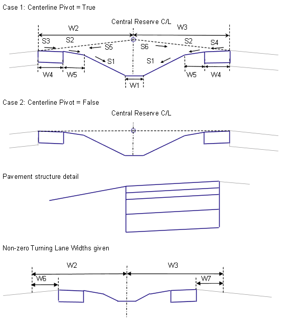
Superelevation Pivot Point
The central reserve can be configured to have the superelevation pivot point at the centerline, or at the inside edges of carriageways. If Centerline Pivot is used, the left and right outside lane superelevation slopes are obtained from the baseline’s superelevation specifications, and the levels of the inside edges of carriageways are calculated by applying these slopes to the left and right central reserve widths from the attachment point. If Centerline Pivot is not used, the edges of carriageways are held to the level of the attachment point.
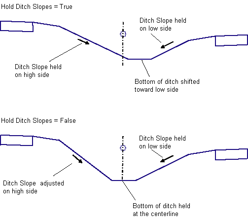
Ditch Levels and Slopes
Superelevation or turning lanes may cause the top of the ditch slopes to be at different levels on the left and right sides, resulting in an asymetrical ditch. There are two options for handling this situation. If Hold Ditch Slopes is set to True, then the given ditch slopes are held constant on both sides, which shifts the bottom of ditch away from the centerline towards the lower side. If set to False, the ditch bottom is centered about the central reserve centerline, the given slope is held on the lower side, and the slope is adjusted to match on the higher side.
Shoulder Treatment
The paved portions of the shoulders follow the slopes defined for the left and right inside shoulder slopes for the baseline alignment’s superelevation specifications. These slopes are applied inward from the inside edges of carriageways. The unpaved portions of the shoulders are fixed at the given Unpaved Shoulder %Slope value.
Superelevation Axis of Rotation Support
This subassembly works only with Carriageway Types that have a Pivot Method of Central Reserve Edges and a Central Reserve Treatment of Maintain Central Reserve Shape. If you use this subassembly with any other Pivot Method or with Distorted Central Reserve Treatment, it will produce a result equivalent to Central Reserve Edges with Maintain Central Reserve Shape.
Layout Mode Operation
In layout mode, this subassembly calculates and displays the central reserve and shoulders based on the input parameters given, and assuming that the lane slopes are -2% and the paved shoulder slopes are -5%.
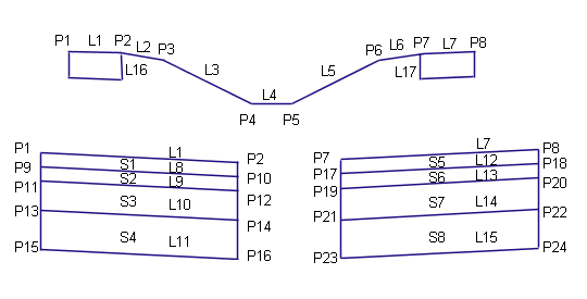
Point, Link, and Shape Codes
The following table lists the point, link, and shape codes for this subassembly that have codes assigned to them. Point, link, or shape codes for this subassembly that do not have codes assigned are not included in this table.
|
Point, Link, or Shape |
Code |
Description |
|---|---|---|
|
P2, P7 |
EPS |
Edges of paved shoulder on finish surface |
|
P10, P17 |
EPS_Pave1 |
Edges of paved shoulder on Pave1 |
|
P12, P19 |
EPS_Pave2 |
Edges of paved shoulder on Pave2 |
|
P14, P21 |
EPS_Base |
Edges of paved shoulder on Base |
|
P16, P23 |
EPS_Sub |
Edges of paved shoulder on Subbase |
|
P3, P6 |
ES_Unpaved |
Edges of gravel shoulder |
|
P4 |
LMedDitch |
Left edge of central reserve ditch |
|
P5 |
RMedDitch |
Right edge of central reserve ditch |
|
L1, L7 |
Top Pave |
Finish surface on paved shoulders |
|
L2 – L6 |
Top Datum |
Finish surface on unpaved shoulder and central reserve links |
|
L8, L12 |
Pave1 |
|
|
L9, L13 |
Pave2 |
|
|
L10, L14 |
Base |
|
|
L11, L15 |
SubBase |
|
|
L11, L15, L16, L17 |
Datum |
Subbase and vertical links on paved shoulders |
|
S1, S5 |
Pave1 |
|
|
S2, S6 |
Pave2 |
|
|
S3, S7 |
Base |
|
|
S4, S8 |
SubBase |
Coding Diagram