This subassembly inserts parabolic travel lanes, to represent finish surface, pavement, and subbase for urban, parabolic lanes between known flange points. The parabolic shape is simulated by a series of short, straight-line links.
To use this subassembly, you should have separate alignments defining the left and right flange points. Levels at these points could come from surfaces or profiles. Furthermore, if the component defining the edges (for example, kerb and channel) is also a rehab component, then they could be passed in as marked points, thus transferring offset and level information.
Attachment
The attachment point is (near) the crown point of the subassembly. Since the subassembly places lanes on either side of the crown, this attachment point is typically at the assembly baseline point. While in the layout mode this point coincides with crown point, in the corridor state the finished design profile point (or baseline marker point) may not be the same as crown point, as crown point offset and level are computed by input data such as left and right (flange point) offset values.
Input Parameters
Note: All dimensions are in meters or feet unless otherwise noted. All slopes are in run-over-rise form (for example, 4 : 1) unless indicated as a percent slope with a “%” sign.
|
Parameter |
Description |
Type |
Default |
|---|---|---|---|
|
Left Flange Offset |
Distance between attachment point to left edge of pavement. This value is used only if no alignment or marked point is associated to left edge. |
Numeric |
7.2m 24.0ft |
|
Right Flange Offset |
Distance between attachment point to right edge of pavement. This value is used only if no alignment or marked point is associated to right edge. |
Numeric |
7.2m 24.0ft |
|
Left Flange – Marked Point |
To provide existing left edge of pavement offset and level to start the subassembly (OPTIONAL) |
String |
None |
|
Right Flange – Marked Point |
To provide existing right edge of pavement offset and level to start the subassembly (OPTIONAL) |
String |
None |
| Crown Height | Height from the center point of the string line to the crown of road. |
Numeric, positive |
0.10m 0.3333ft |
|
Min %Slope |
Minimum % crossfall allowed for the lanes, in the outward direction from the attachment point. |
Numeric |
-1% |
|
Max %Slope |
Maximum % crossfall allowed for the lanes, in the outward direction from the attachment point. |
Numeric |
-4% |
| Overlay Depth |
Depth of overlay below the finish surface. |
Numeric, positive |
0.025m 0.083ft |
| No. Increments | Number of straight line increments simulating the parabolic shape |
Numeric, positive, even |
8 |
If target parameters are provided, the parameters above (namely default offsets and marked points) will be ignored as applicable.
Target Parameters
This section lists the parameters in this subassembly that can be mapped to one or more target objects, such as a surface, alignment, or profile object in a drawing. For more information, see in the AutoCAD Civil 3D User’s Guide Help.
|
Parameter |
Description |
Status |
|---|---|---|
|
Left Channel Point |
This will provide left edge of pavement offset value with respect to the attachment point. The following object types can be used as targets for specifying this offset: alignments, polylines, feature lines, or survey figures. |
Optional |
|
Right Channel Point |
This will provide right edge of pavement offset value with respect to the attachment point. The following object types can be used as targets for specifying this offset: alignments, polylines, feature lines, or survey figures. |
Optional |
|
Left Channel Profile |
This will provide left edge of pavement level value with respect to the attachment point. The following object types can be used as targets for specifying this level: profiles, 3D polylines, feature lines, or survey figures. |
Optional |
|
Right Channel Profile |
This will provide right edge of pavement level value with respect to the attachment point. The following object types can be used as targets for specifying this level: profiles, 3D polylines, feature lines, or survey figures. |
Optional |
|
EGTopSurf |
If profiles are not supplied for left/right edge of pavement levels, then this surface level at that offset will be picked up as level value (for left/right) respectively. The following object types can be used as targets for specifying this surface: surfaces. |
Required |
Output Parameters
None
Behavior
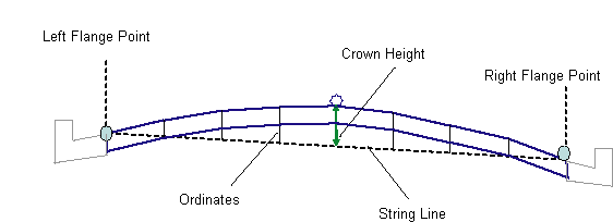
Initial attachment point is just a place holder (and more applicable in layout mode). First two points to establish are left and right edges, whose offsets and levels are determined based on input parameters.
Then a string line is defined by joining the left and right flange points (which are newly established edges of carriageways). This string line is divided by "number of increments" parameter and middle one is taken as "crown point" offset. Crown point level is established by adding the 'crown height" parameter to the level of midpoint on the string line.
The ordinates of the parabolic curve at other tesselated points are calculated using standard vertical curve equations, based on the assumption that the string line is horizontal. Straight line links are added to connect the ordinate points in a series (from left edge to crown point to right edge) to define the finish surface. A parallel surface is inserted at the overlay depth below this finish surface.
Layout Mode Operation
In layout mode, this subassembly inserts equal number (based on input parameter) lanes on either side of the attachment point. First two edge points will be located based on left/right offsets. These left and right point levels are calculated (in layout mode) by subtracting crown height from the ordinate of attachment point. Then the "Crown Point" is located halfway between these two points. However, since the programatic defaults are the same for both left and right, by default the crown point matches with attachment point. Lane slopes are accepted as they come in. Thickness of pavement is equal to overlay depth.
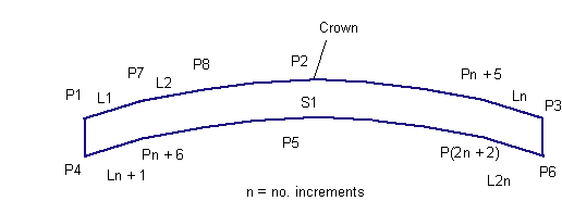
Point, Link, and Shape Codes
The following table lists the point, link, and shape codes for this subassembly that have codes assigned to them. Point, link, or shape codes for this subassembly that do not have codes assigned are not included in this table.
|
Point, Link, or Shape |
Code |
Description |
|---|---|---|
|
P1, P3 |
EC |
Outside edges of lane on finish surface |
|
P4, P6 |
EC_Overlay |
Outside edges of lane on the Base surface |
|
P2 |
Crown |
Crown point on finish surface |
|
P5 |
Crown_Overlay |
Crown point on Pave1 |
|
L1 to Ln |
Top, Pave |
Links connecting all points on finish surface |
|
L(n+1) to L(2n) |
Overlay |
Links connecting all points on bottom of overlay surface |
|
S1 |
Overlay |
Area between finish surface and Pave1 |
Coding Diagram