This subassembly inserts one or more travel lanes outward from an alignment that defines the edge of a central reserve.
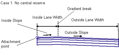
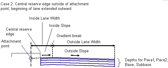
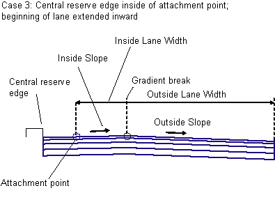
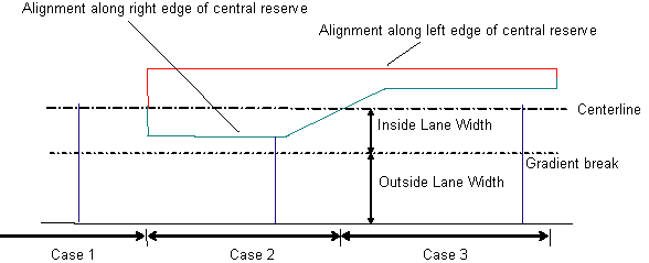
The alignment defining the edge of the central reserve may at times be either not present (Case 1), outside the carriageway centerline (Case 2), or inside the centerline (Case 3).
To use this subassembly, you should have separate alignments defining the left and right edges of the central reserve. It may be necessary to define separate corridor model regions for each individual central reserve. This subassembly differs from LaneFromTaperedCentralReserve1 in that it provides for a gradient break with different slopes in the travel lanes.
Attachment
The attachment point is at the location where the inside edge of carriageway would be if there was no central reserve. This is typically at the assembly baseline.
Input Parameters
Note: All dimensions are in meters or feet unless otherwise noted. All slopes are in run-over-rise form (for example, 4 : 1) unless indicated as a percent slope with a “%” sign.
|
Parameter |
Description |
Type |
Default |
|---|---|---|---|
|
Side |
Indicates the outward direction of the lane |
Left / Right |
Right |
|
Inside Lane Width |
Width of the inside lane for the condition where there is no central reserve; that is, from the attachment point to the gradient break point. |
Numeric |
3.6 m 12.0 ft |
|
Inside Lane - Use Superelevation Slope |
Specifies to use the superelevation slope for the inside lane. Choices are No, Outside Lane Slope, and Inside Lane Slope. |
String |
Inside Lane Slope |
|
Default Inside Slope |
Specifies default slope for the inside lane. This value is used if superelevation slope is not used, or is not specified for the baseline alignment. |
Numeric, positive |
2.0% |
|
Outside Lane - Use Superelevation Slope |
Specifies to use the superelevation slope for the outside lane. Choices are No, Outside Lane Slope, and Inside Lane Slope. |
String |
Outside Lane Slope |
|
Default Outside Slope |
Specifies default slope for the outside lane, if superelevation slope is not specified. |
Numeric, positive |
- 2.0% |
|
Outside Lane Width |
Width from the gradient break point to the outside edge of carriageway. |
Numeric |
3.6 m 12.0 ft |
|
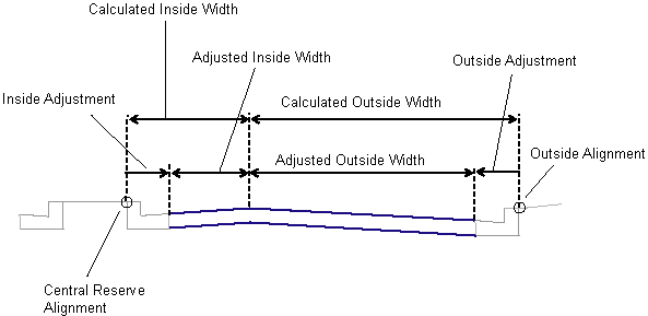
Inside Adjustment |
Used if the Central Reserve Edge alignment is at a fixed offset from the actual edge of carriageway (for example, at the back of kerb). Adjusts the calculated Inside Lane Width to account for the offset (see diagram). |
Numeric, positive |
0.0 |
|
Outside Adjustment |
Used if the Outside Lane Width alignment is at a fixed offset from the actual edge of carriageway (for example, at the back of kerb). Adjusts the calculated Outside Lane Width to account for the offset (see diagram). |
Numeric, positive |
0.0 |
|
Pave1 Depth |
Depth between finish gradient and Pave1 (zero to omit) |
Numeric, non-negative |
0.025 m 0.083 ft |
|
Pave2 Depth |
Depth between Pave1 and Pave2 (zero to omit) |
Numeric, non-negative |
0.025 m 0.083 ft |
|
Base Depth |
Depth between Pave1 and Base (zero to omit) |
Numeric, non-negative |
0.100 m 0.333 ft |
|
Subbase Depth |
Depth of the Subbase layer at the attachment point (zero to omit) |
Numeric, non-negative |
0.300 m 1.0 ft |
Note that if the Inside %Slope value is always the same as Outside %Slope, or if Inside Lane Width is zero, then the simpler LaneFromTaperedCentralReserve1 subassembly can be used instead.
Target Parameters
This section lists the parameters in this subassembly that can be mapped to one or more target objects.
|
Parameter |
Description |
Status |
|---|---|---|
|
Central Reserve Edge |
May be used to shift the starting offset of the lane to follow an edge-of-central reserve alignment. The following object types can be used as targets for specifying this: alignments, polylines, feature lines, or survey figures. |
Optional |
|
Inside Lane Width |
May be used to override the fixed Inside Lane Width and tie the gradient break to an offset alignment. The following object types can be used as targets for specifying the width: alignments, polylines, feature lines, or survey figures. |
Optional |
|
Outside Lane Width |
May be used to override the fixed Outside Lane Width and tie the edge-of-lane to an offset alignment. The following object types can be used as targets for specifying the width: alignments, polylines, feature lines, or survey figures. |
Optional |
|
Outside Level |
May be used to override the normal lane slope and tie the outer edge of the travel lane to the level of a profile. The following object types can be used as targets for specifying the level: profiles, 3D polylines, feature lines, or survey figures. |
Optional |
Output Parameters
|
Parameter |
Description |
Type |
|---|---|---|
|
Superelevation Axis of Rotation |
Indicates whether the subassembly supports the axis of rotation calculation. To view a description of the parameter, in the Properties window, hover the cursor over the parameter. For more information, see Profile Gradient Line Adjustments During Superelevation. |
Static (Description) |
|
Inside Lane Width |
Width of the inside lane |
Numeric |
|
Inside Lane %Slope |
% slope of the inside lane |
Numeric |
|
Outside Lane Width |
Width of the outside lane |
Numeric |
|
Outside Lane %Slope |
% slope of the outside lane |
Numeric |
Behavior
Gradient Break: The width from the attachment point outwards to the gradient break between the inside and outside lanes can be defined by a fixed numeric width, or an alignment can be used to override the width. The level at the gradient break is determined by applying the specified slope for the inside lane across the width of the lane.
Outside Edge of Carriageway: The width to the outside edge of carriageway can be defined by a fixed numeric width, or an alignment can be used to override the width. The level is determined by applying the specified slope for the width of the lane, unless an Outside Level profile is given. In that case, the outside edge level is tied to the profile, and the slope is adjusted.
Inside Edge of Carriageway: The location of the inside edge of carriageway is calculated based on the three cases shown in the previous diagram. If a Central Reserve Edge alignment is given, and that alignment is outside of the lane’s attachment point, the inside edge is shifted outward from the attachment point at the lane slope (Case 2). If the Central Reserve Edge alignment is inside of the lane’s attachment point, the inside edge is shifted inward from the attachment point at the inside lane slope (Case 3). If no Central Reserve Edge alignment is given, or the given one is not found at a chainage, the inside edge is held at the attachment point (Case 1).
Inside and Outside Adjustments: The Inside Adjustment and Outside Adjustment parameters are provided in case the alignments used for the inside or outside edges are at a fixed offset from the actual edge of carriageway. For example, the alignment being used for the Central Reserve Edge may be at the back-of-kerb instead of at the pavement edge. In this case, the Inside Adjustment parameter should be set to the width of the kerb.
Layout Mode Operation
In layout mode, this subassembly displays the links comprising the lanes for the given widths and slopes. If a superelevation slope is given (LI or LO), the links are displayed at a slope of -2%.
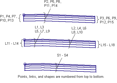
Point, Link, and Shape Codes
The following table lists the point, link, and shape codes for this subassembly that have codes assigned to them. Point, link, or shape codes for this subassembly that do not have codes assigned are not included in this table.
|
Point, Link, or Shape |
Code |
Description |
|---|---|---|
|
P1, P3 |
EC |
Edges of lane on finish surface |
|
P4, P6 |
EC_Pave1 |
Edges of lane on Pave1 layer |
|
P7, P9 |
EC_Pave2 |
Edges of lane on Pave2 layer |
|
P10, P12 |
EC_Base |
Edges of lane on Base layer |
|
P13, P15 |
EC _Sub |
Edges of lane on Subbase layer |
|
P2 |
Crown |
Crown (gradient break) on finish surface |
|
P5 |
Crown_Pave1 |
Crown (gradient break) on Pave1 |
|
P8 |
Crown_Pave2 |
Crown (gradient break) on Pave2 |
|
P11 |
Crown_Base |
Crown (gradient break) on Base |
|
P14 |
Crown_Subbase |
Crown (gradient break) on Subbase |
|
L1, L2 |
Top, Pave |
Finish surface |
|
L3, L4 |
Pave1 |
Pave1 surface |
|
L5, L6 |
Pave2 |
Pave2 surface |
|
L7, L8 |
Base |
Base surface |
|
L9, L10 |
SubBase, Datum |
Subbase surface |
|
S1 |
Pave1 |
Area between finish surface and Pave1 |
|
S2 |
Pave2 |
Area between Pave1 and Pave2 |
|
S3 |
Base |
Area between Pave2 and Base |
|
S4 |
SubBase |
Area between Base and Subbase |
Coding Diagram