The mParticles Glue test creates bindings between particles, thus serving as a "glue" for particle matter. With mParticles Glue, particles tend to stay together in their original formation, but can break apart during the simulation based on physical actions or the influence of the mParticles Solvent operator. Like many other tests in Particle Flow, you can use mParticles Glue without necessarily connecting it to another event, in which case it functions as an operator.
mParticles Glue provides two basic ways to bind particles: flexible and rigid. Rigid mode (Binding type=Rigid or Simplified) firmly maintains the positions of particles relative to each other, while in flexible mode (Binding type=Distance), particles have more freedom to move around each other.
See also:
mParticles Glue Test: Distance Binding Rollout
mParticles Glue Test: Rigid/Simplified Binding Rollouts
mParticles Glue Test: Wiring To/From Data Channels Rollouts
Important Glue Points
mParticles Glue is one of the most important and complex elements of physics simulation in Particle Flow, so it's important to be aware of how the various factors work together, both within Glue and with the rest of the system. As you work with mParticles Glue, keep these considerations in mind:
- When first setting up a simulation with mParticles Glue, always turn on Visualize Binding (see below) so you can see which particles are bound together.
- Numeric instabilities are inherent in the system, causing motion where you might not expect any, but there are ways you can reduce or eliminate such motion. The first and most important is the Subframe Factor setting on the mParticles World helper
 Advanced Parameters rollout. A good general formula is [Subframe Factor] = 2 * [Max Binds p/Particle] + 2. So if Max Binds p/Particle is set to 4, then set Subframe Factor to 10 (2*4 + 2).
 - If adjusting the Subframe Factor setting doesn't help, your setup might be experiencing phantom torque momentum, which you can resolve with the mParticles Drag operator. Add it to the event in question and then increase the Damping Factor
 Angular setting until the particle system stabilizes.
 - For particles to bind to a deflector, the deflector must be a part of any mParticles Collision test in the same mParticles World simulation.
Interface

Binding group
- Type
- Defines the major classes of bindings used by an mParticles Glue operator. The available choices are Distance, Rigid, and Simplified. Each type has its own rollout with additional parameters relevant to that binding type.
- Distance Use this method to maintain a specified distance between two points on two simulation items: particle-particle, particle-deflector, or particle-ground, based on the To Bind With group settings (see following). This typically results in relatively flexible bindings, to simulate materials such as cloth.
In some cases you might see springy behavior with Distance binding, where particles pull apart temporarily and then move back together spontaneously. To prevent this, increase the Subframe Factor value on the mParticles World helper
 Advanced Parameters rollout.
 For Distance-related settings, see Distance Binding Rollout.
- Rigid This binding type permits no relative movement between two simulation items. However, depending on other simulation parameters, there is some leeway in relative positioning, which you can use to apply flexibility to the rigid binding.
Specifically, the parameters that affect the leeway in relative positioning are the Subframe Factor value on the mParticles World helper
 Advanced Parameters rollout (increase the value to reduce flexibility) and the Solve Factor setting on the Rigid Binding rollout.
 Also, you can control flexibility with the binding geometry itself. For example, a one-brick-thick wall is more flexible than a two-brick-thick wall because all bindings for the former lie on a plane (2D structure). Bindings in the double-thick wall, however, form a more stable 3D structure.
For Rigid-related settings, see Rigid/Simplified Binding Rollouts.
- Simplified Similar to Rigid, but uses a simpler simulation solver that results in faster simulation at the cost of accuracy in relative positioning (more flexing of rigid bindings due to inaccuracy in the solver).
For Simplified-related settings, see Rigid/Simplified Binding Rollouts.
For videos showing the effects of using the different Binding Type options and Subframe Factor values, see Binding Type.
- Distance Use this method to maintain a specified distance between two points on two simulation items: particle-particle, particle-deflector, or particle-ground, based on the To Bind With group settings (see following). This typically results in relatively flexible bindings, to simulate materials such as cloth.
- Timing
- Defines when new bindings are formed.
- On Event Entry Bindings are created for each particle at the moment that it enters the event. The new particle is bound to all particles; both "old" (already in the event) and "new" (also just entered the event). Once the binding is defined, a particle cannot gain any new bindings to particles already present in the event.
When all particles are generated at once, as with the Birth Grid operator, the bindings are also defined at once. When a continuous stream of particles enters an event, new bindings can be generated between new and old particles if the new particles are close enough to the old ones.
- Continuous The operator checks for potential new bindings at every integration step, and the check involves all particles in the current event.
For a video showing the effects of the Timing option, see Timing.
- On Event Entry Bindings are created for each particle at the moment that it enters the event. The new particle is bound to all particles; both "old" (already in the event) and "new" (also just entered the event). Once the binding is defined, a particle cannot gain any new bindings to particles already present in the event.
- Bind Distance
- The distance from a particle within which mParticles Glue checks for other particles that can be bound to it.
For a video showing the effects of the Bind Distance value, see Bind Distance.
During the first stage of generating bindings—finding candidates for binding—the number of the potential binding-partner particles cannot exceed the Max Binds p/Particle value, and might be even less if a particle already has bindings that were generated before the current frame. When considering a binding to the ground or a deflector, the distance is measured from the particle's center to the closest point on the surface of the ground or a deflector.
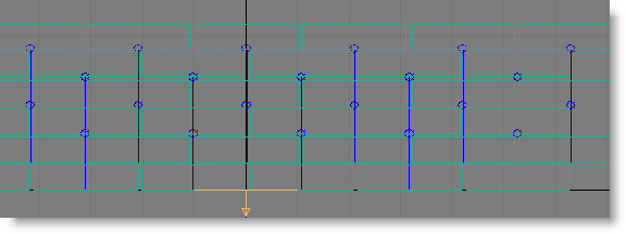
Tip: When adjusting Bind Distance, Bind Gap, and Bind Center Aligned Only, it's often helpful to turn on the Visualize Binding option (see following). When Visualize Binding is on, bindings are depicted as lines and other symbols, using the color of the swatch next to the Visualize Binding check box, as shown in the following illustrations.In the following illustration, a wall of bricks uses a low Bind Distance value, so the bindings are relatively unstable:
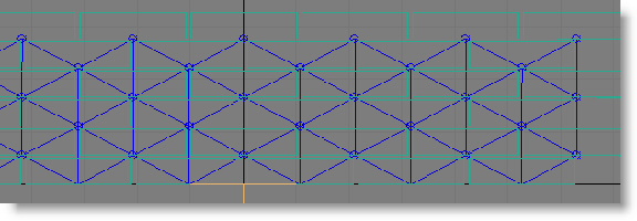
By increasing the Bind Distance value, you get diagonal bindings as well as vertical ones, improving the stability of the structure:
- Bind Gap
- The second, optional stage of generating bindings takes into account particle orientations and collision shapes (as opposed to rendered shapes). When Bind Gap is on, then, in order to be bound, the distance between particle shapes must be less than the Bind Gap value. Because this option deals with particle shapes, simulation can be slow if particles have complex collision shapes such as Convex Hull.
For an example of using Bind Gap, see the mParticles Quick Start tutorial, which uses Bind Gap in conjunction with Bind Center Aligned Only (see following) to allow particles to bind in the horizontal direction only.
For a video showing the effects of the Bind Gap value, see Bind Gap.
- Bind Center Aligned Only
- When on, binding occurs only between particles that are aligned to each other. For each pair of particles (say, Particle A and Particle B), the software determines alignment by drawing an imaginary line from Particle A's pivot to the closest point on an extrapolated extension of Particle B's local axis that comes nearest to Particle A's pivot, and then reverses the process using Particle B's pivot and Particle A's local axes. If the length of neither imaginary line in world units does not exceed the Align Margin value, mParticles Glue considers the particles to be aligned, and binds only those particles.
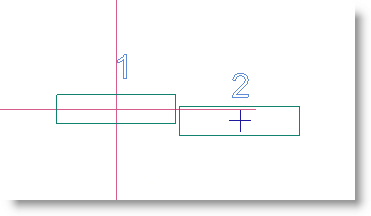
The following illustration shows an example of how Bind Center Aligned Only works. It depicts two brick-type particles: 1 and 2. The red cross shows brick 1's local axes, extended to pass by brick 2's pivot, shown as a smaller blue cross. If the distance between brick 2's pivot and the closest point on the nearest extended axis of brick 1 is equal to or less than the Align Margin distance, then mParticles Glue considers their centers to be aligned for binding purposes.
- Align Margin
- Defines the closeness factor in world units, and measures the distance between one particle's local axis and the other particle's pivot position (as the distance between an infinite line and a point). The distance between the extended axes of two particles must not exceed this value for particles to be considered aligned.
For a video showing the effects of the Align Margin setting, see Align Margin.
- Allow Binding Penetration
- Defines whether bound-together particles can interpenetrate. When on, the simulation engine allows the particle shapes to overlap. When off, the particles cannot overlap; instead, they collide. The same applies to a particle bound to a deflector or the ground.
For a video showing the effects of the Allow Binding Penetration option, see Allow Binding Penetration.
- Max Binds p/Particle
- The greatest number of binding candidates that the software considers for each particle, within the Bind Distance. This can affect the particle arrangement after binding; you might want to experiment with it to find the best value for your simulation.
When To Bind With group
 Deflectors and/or Ground binding options are on (see following), this limit is ignored in defining whether a particle can be bound to a deflector and/or the ground. In this sense, bindings to deflectors and the ground have a higher priority than regular particle bindings. However, if a particle binds to a deflector and/or the ground, these "VIP" bindings are counted as a part of the total number of bindings for a particle, so it can restrict the number of particles a particle can bind to. Tip: Allowing a large number of bindings for a particle makes the simulation more complex and potentially unstable because more counter-forces are applied to a particle. For optimal stability and accuracy in simulations that use bindings, it's recommended that you increase the Subframe Factor setting in mParticles World helper. A good general formula is [Subframe Factor] = 2 * [Max Binds p/Particle] + 2. So if Max Binds p/Particle is set to 4, then set Subframe Factor to 10 (2*4 + 2).
For a video showing the effects of the Max Binds p/Particle, see Max Binds p/Particle.
- Visualize Binding
- When on, bindings appear in the viewports as lines between bound entities using the specified color; to change the color, click the color swatch. To best see the links, set the viewport to Wireframe display, if necessary, or even Bounding Box.
Visualize Binding is useful as a debugging tool when you want to see the results of the mParticles Glue test settings: Which particles are bound to which. The status of the check box does not affect the simulation itself, but when on, the option can slow down playback. The option is relevant only for viewports; it does not affect the rendered output.
Flexible and rigid bindings are displayed differently. Rigid bindings connect particle positions with a line segment, placing a circle marker at a particle position. If a particle and a deflector or ground are bound by a rigid binding, a line segment is drawn between the particle position and closest deflector/ground surface point. Each flexible binding is drawn as a line between anchor binding points, with square markers at the anchor positions.
You can find more information about anchor points in the following two topics, which cover the binding-type-specific rollouts: mParticles Glue Test: Distance Binding Rollout and mParticles Glue Test: Rigid/Simplified Binding Rollouts.
Tip: You can toggle the visibility of all bindings associated with a particular mParticles World helper with the Hide Visual Representation Particle Bindings setting on the helper's Parameters rollout (at the bottom of the rollout). Tip: Visible bindings do not render, but you can make them show up in animation previews. On the Make Preview dialog, turn on Display In Preview group
 Helpers.
 - Bake Binding / Unbake / ?
- Generation of bindings is a CPU-intensive process—the test has to check for bindings among all particles in the event to find those that satisfy the specified conditions.
To avoid having to repeat these calculations every time you run the simulation, you can precalculate and save binding information by clicking Bake Binding. mParticles Glue makes a record of all bindings in the current frame, and uses this information subsequently in determining whether to bind a pair of particles when they enter the event.
After you bake the bindings, most parameters in the Binding group become unavailable because they no longer define binding conditions; the binding conditions are defined by the baked data. The one exception is Max Binds p/Particle, which remains available after baking, so you can reduce (but not increase) the maximum number of binds per particle in the baked solution.
To delete the baked data, click Unbake, and to view the recorded binding statistics, click the ? button.
The binding record is saved with the scene file, which typically results in larger files, and the next time you load the file, the binding record is again used as a binding guide.
Breakability group
Simply binding particles together is usually not enough for visual effects. The ability to break the bound particles apart is also crucial, preferably if the force imposed on the particle binding exceeds a certain level. The parameters in the Breakability group define the impact force thresholds.
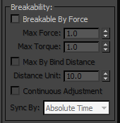
- Breakable By Force
- When on, the remaining Breakability settings become available and let you specify the conditions under which bindings can be broken. For natural, random-looking breakage, the two most important settings are Max Force and Max Torque. Tip: In most simulations, to make the bindings less breakable you need to increase both Max Force and Max Torque.
- Max Force
- The maximum linear force that a binding can withstand before breaking. This is the force that pulls the particles apart.
- Max Torque
- The maximum angular force that a binding can withstand before breaking. This is the force that twists and/or bends particles.
For videos showing the effects of the Max Force and Max Torque values, see Max Force and Max Torque.
- Max By Bind Distance
- Allows the simulation to take into account the distance between each pair of particles, using it as an additional factor to set up the maximum force values.
For example, in a brick wall, the force required to break apart vertically adjacent bricks (in the next higher or lower layer) should be greater than the force required to break apart horizontally adjacent bricks (in the same layer) because there's more surface area, and thus more mortar, between the former than between the latter.
- Distance Unit
- The distance between particles (that is, their centers) at which to apply the specified Max Force/Torque values.
With greater and smaller distances, Max Force/Torque are applied in inverse proportion. So, for example, if particles are twice as far apart as specified by the Distance Unit value, the applied Max Force/Torque values are half the specified ones.
In the following illustration, the distance between particles 1261 and 1260 is larger than distance between particles 1261 and 1237. As a result, when Max By Bind Distance is on, the binding between 1261 and 1237 will be stronger then the binding between 1261 and 1260.
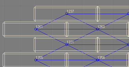
For a video showing the effects of the Max By Bind Distance option, see Max By Bind Distance.
- Continuous Adjustment
- You can animate the Max Force and Max Torque settings; however, by default the current values of these settings are established as constant values for the force and torque thresholds at the moment a binding is generated. If you want the ability to adjust force and torque threshold values constantly, after bindings have been generated, turn On Continuous Adjustment. This way the force/torque thresholds are constantly adjusted, and if at any given frame the current threshold values fall below the actual force/torque exerted on a binding then the binding is broken.
- Sync By
- When using the Continuous Adjustment option, use Sync By to choose the time frame in which to apply animation of the Max Force/Torque values: Absolute Time, Event Duration, or Particle Age. For details, see the main 3ds Max help (for instance, the Scale Operator topic
 Animation Offset Keying group section).
 For a video showing the effects of the Continuous Adjustment option, see Sync By.
Test True When Particles group
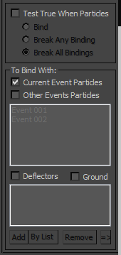
- Test True When Particles
- When on, mParticles Glue also serves as a test, redirecting particles to the next event based on the particle bindings in the event and which option is active:
- Bind Once a particle gets any binding—to another particle, a deflector, or the ground—it's ejected to the next event right away. Note: Binding is a persistent property for a particle, so a particle keeps the binding while in the next event. Also, the property that determines how bindings can break, as defined by Max Force and Max Torque settings, also persists; if sufficient forces are applied to a particle in the next event, the binding can be broken. However, the Continuous Adjustment update (see preceding) no longer applies to a particle binding in the next event; it keeps the force/torque threshold values at the moment when a particle left the current event.
- Break Any Binding Occurs when a particle breaks any of its bindings; as with the Bind condition (see preceding), a particle keeps other bindings intact when redirected to the next event.
- Break All Bindings Occurs when a particle loses all of its bindings.
For a video showing the effects of the Test True When Particles option, see Test True When Particles.
- Bind Once a particle gets any binding—to another particle, a deflector, or the ground—it's ejected to the next event right away.
To Bind With group
The settings in this group let you specify which other simulation entities a particle can bind with. It can be particles in the current event, particles in other events, deflectors, the ground, or any combination thereof.
For a video showing the effects of the options in the To Bind With group, see To Bind With group.
- Current Event Particles
- When on, particles in the current event can bind with other particles in this event. This is the only To Bind With option that's on by default.
- Other Events Particles
- When on, particles in the current event can bind with particles in other events that are highlighted in the list. For example, if you want particles in this event to bind only with particles in events 03 and 05, turn on Other Events Particles, highlight Event 03 and Event 05 in the list, and turn off all other To Bind With options. Note: For technical reasons, the Other Events Particles list always lists all events, not just events other than the one containing the mParticles Glue test. If you want bindings among particles in the current event as well as particles in other events, turn on Current Event Particles and Other Events Particles, and highlight only the other events in the Other Events Particles list.
- Deflectors
- When on, particles in the current event can bind with any deflector in the list; add deflectors with the Add or By List button. To create a deflector, apply the PFlow Collision Shape (WSM) modifier to a standard mesh object; this object can then interact with particles in the MassFX simulation. Important: For particles to bind to a deflector, the deflector must be a part of any mParticles Collision test in the same mParticles World simulation.
- Ground
- When on, particles in the current event can bind to the ground, as defined by the master mParticles World helper. Thus, the Ground Collision Plane option must be on in the helper's parameters. Note: The Ground option is unavailable when Binding
 Type is set to Distance. As a workaround, place a thin box on the ground under the particles, apply the PFlow Collision Shape (WSM) modifier, and specify it as a deflector (see preceding).
 - Add/By List/Remove/=>
- Use these buttons to edit the list of deflectors. To populate the list, click Add and then select an object, or click By List to open a selection dialog and choose objects in the list.
To remove an object from the list, highlight it and click Remove, and to select an object in the list, showing its parameters on the Modify panel, highlight it and click the => button.