- After the job has completed, open the file pedal_assembly.wbpj.
- Right-click Model in the Static Structural system and select Edit.
- When ANSYS Mechanical opens, select Solution from the model tree.
- Click Tools > Read Results Files and locate the pedal_assembly_ame.rst file.
- Click User Defined Result and enter SVAR12 in the Expression box. SVAR12 represents the strength reduction factor for the points that lie on the weld surface.
- Set the Display Time to 0.005 seconds.
- Right-click User Defined Result in the model tree and select Evaluate All Results.
- When the results are displayed, select the Capped IsoSurfaces geometry plot and click the Top Capped IsoSurface icon.
- Select the
Show Undeformed Model option in the Edges drop-list.
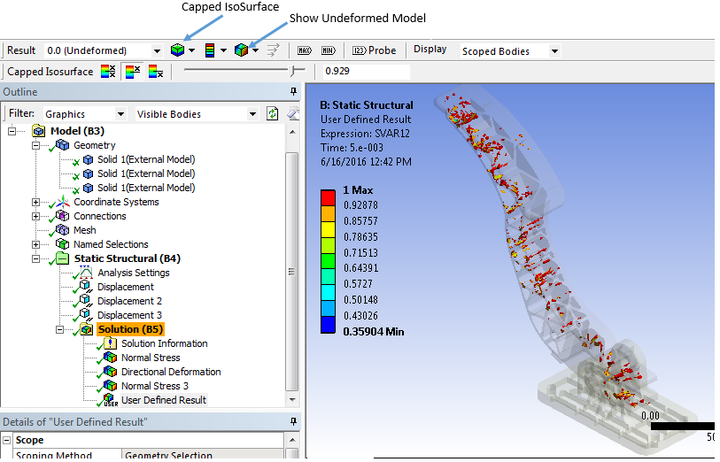
Now we can see the strength reduction factors for each point on the weld surface. Notice that the strength reduction factor is near 1 for the majority of the model, indicating the processing conditions used in the injection molding simulation were of good quality.
The Extron 3019 HS material used in this tutorial was characterized for use with tension and compression. Let's view the compressive response by plotting the S22 component of the stress for one of the elements loaded in compression.
- Select Solution from the model tree.
- Add a new Normal Stress result (Solution > Stress > Normal Stress).
- Change the Orientation to Y-Axis.
- Right-click
Normal Stress in the model tree and select
Evaluate All Results.
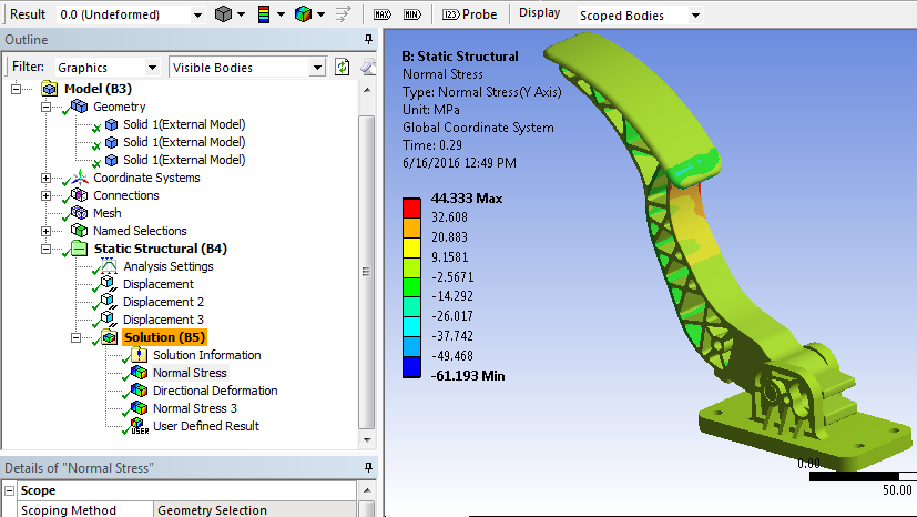
- Select a single element loaded in compression. Right-click and Insert a new Normal Stress about the Y-Axis for the selected element.
- Evaluate results again and plot the Minimum value of the normal stress. Results will vary depending on the element selected.
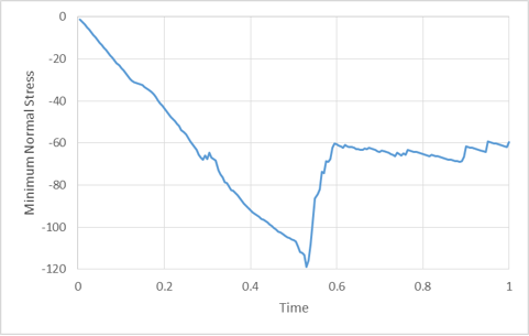
Notice how the element experiences a load drop when the compressive failure criterion is triggered. After the load drop, the plasticity response continues to evolve as before. Since there is still a physical interference between the materials when loaded in compression, this behavior makes sense. Refer to the Compression section of the Theory Manual for more information on how the compressive material model is implemented.