Use the Create Composite Material GUI to create a composite material.
Each composite material processed by Helius PFA is considered by Abaqus to be a user-defined material. The Create Composite Material GUI provides a simple means of creating these composite material definitions in the Abaqus input file. It allows you to select a material from the composite material database and then select a number of different options for the multiscale constitutive relations that are used to define the thermo-mechanical response of the composite material.
To open the Create Composite Material GUI from within Abaqus/CAE, go to the main toolbar and select . The GUI will appear as shown below.
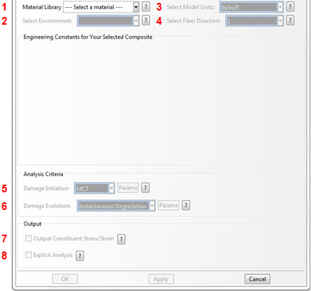
As shown above, there are several options involved in using the Create Composite Material GUI to define a composite material type for Helius PFA. Each of the options is discussed below.
- Composite Material Selection - Select a composite material from the Helius PFA material library. If the material library does not contain a composite material that you would like to use in an analysis, a material data file must first be created and added to the material library (refer to the Material Manager User's Guide). Once a composite material is selected, the homogenized (or composite average) engineering constants for that material will be displayed in the GUI.
- Environment Selection - If the selected material contains material properties for multiple environments (combination of temperature and moisture), you should select the environment that you wish to use during the analysis. Once selected, the material properties for the environment will be displayed in the GUI.
- System of Units - Select the system of units that should be used to compute constitutive relations and stresses. By default, Helius PFA expresses constitutive relations and computes stress in the (N/m/K) system of units. If the finite element model is created using a different system of units, Helius PFA must convert its constitutive calculations to the system of units required by the model. For such purposes, Helius PFA contains conversion factors for four commonly used systems of units: N/m/K, N/mm/K, lb/in/R, and lb/ft/R. If the finite element model uses one of these four systems of units, you must select the appropriate system from the drop-down list. In the event that the model's system of units does not appear in the drop-down list, you should select the default system of N/m/K and then refer to The HIN File section for details on how to use the HIN file to define a custom set of units.
-
Principal Material Coordinate System -
Helius PFA expresses constitutive relations and computes stresses in the principal material coordinate system of the composite material. Here you select one of two or three possible orientations for the composite's principal material coordinate system.
For Unidirectional Microstructures: The default principal material coordinate system is oriented with the '1' direction aligned with the fiber direction, while the '2' and '3' directions lie in the material's plane of transverse isotropy. This default orientation of the principal material coordinate system corresponds to the selection of "1" from the fiber direction drop-down menu. However, in situations where it adds convenience or simplicity to the model creation process, you may change the orientation of the principal material coordinate system so that the '2' direction is aligned with the fiber direction, while the '1' and '3' directions lie in the composite material's plane of transverse isotropy. This particular orientation of the principal material coordinate system corresponds to the selection of "2" from the fiber direction drop down menu. If you select the value '2' from the drop-down list, the transformed properties are displayed in the GUI.
For Woven Microstructures: The default principal material coordinate system is oriented with the '1' direction aligned with the fill tow direction, while the '2' direction corresponds to the warp tow direction, and the '3' direction corresponds with the out-of-plane direction. This default orientation of the principal material coordinate system corresponds to the selection of "1" from the fiber direction drop down menu. However, in situations where it adds convenience or simplicity to the model creation process, you may change the orientation of the principal material coordinate system so that the '2' direction is aligned with the fill tow direction, while the '1' direction corresponds to the warp tow direction. This particular orientation of the principal material coordinate system corresponds to the selection of "2" from the fiber direction drop-down menu. Additionally, you may change the orientation of the principal material coordinate system so that the '3' direction is aligned with the fill tow direction while the '2' direction corresponds to the warp tow direction. This particular orientation of the principal material coordinate system corresponds to the selection of "3" from the fiber direction drop down menu.
-
Damage Initiation Criterion Selection - Choose which failure criterion you would like to use for the selected material. The criterion chosen only dictates the initiation of failure and not the progression of damage. For unidirectional composites the available options are:
- User (see the Installation and Operations Guide)
- MCT (default)
- Max Stress
- Max Strain
- Tsai-Hill
- Tsai-Wu
- Christensen
- Hashin
- Puck
- LaRC02
For woven composites the available options are:- User (see the Helius PFA User Subroutines manual)
- MCT (default)
- Max Stress
- Max Strain
See the Theory Manual for technical information about each criterion.
The "Params" button will become available if a selected criterion has additional parameters that must be provided. By clicking this button a new window will open allowing you to define the parameters required for the selected criterion. The parameters that must be defined for each criterion are:- MCT
- Pressure Induced Strength Enhancement (unidirectional composites only) - Choose whether or not to account for the experimentally observed strengthening of the composite in the presence of a hydrostatic compressive stress. If you check this box, Helius PFA monitors the hydrostatic compressive stress level in the matrix constituent. If the hydrostatic compressive stress level in the matrix constituent exceeds a threshold value, then the strength of both the matrix constituent and the fiber constituent are scaled upwards commensurate with the level of hydrostatic compressive stress level in the matrix constituent. For further information on Hydrostatic Strengthening of the composite, refer to Appendix A and the Theory Manual. This feature is not supported for materials in Abaqus/Explicit analyses.
-
Pre-Failure Nonlinearity - Choose whether or not to account for the nonlinear longitudinal shear stress/strain response that is commonly observed in fiber-reinforced composite materials. If you check this box, Helius PFA will employ a four-segment (unidirectional) or seven-segment (woven), piecewise linear representation of the longitudinal shear stress/strain response (i.e.,
 vs.
vs.
 , and
, and
 vs.
vs.
 ), while the responses of the other four stress and strain components remain unaffected by this feature. The entire series of discrete reductions in the longitudinal shear moduli of the composite is conducted in such a way that the piecewise linear longitudinal shear response closely matches experimentally measured longitudinal shear data for the composite.
It should be emphasized that this feature is only available for composite materials where a longitudinal shear stress/strain curve was supplied during the MCT material characterization process. If this feature is requested for a composite material that was characterized without a longitudinal shear stress/strain curve, Helius PFA will issue an error message at runtime and execution will halt. For further information on the Pre-Failure Nonlinearity feature, refer to Appendix A of this User's Guide, the Theory Manual, and Example Problem 2. For further information on characterizing new composite materials with Pre-Failure Nonlinearity capability, please refer to the Material Manager User's Guide. This feature is not supported for materials in Abaqus/Explicit analyses.
-
Tsai Wu
- f* - Cross product term. This value must be in the range: 0.5 ≤ f* ≤ 0.0 and is only used if σbiax is zero.
- σbiax - Equibiaxial stress at failure. If unknown this value can be left as zero.
-
Hashin
- α - Specifies the amount of contribution from the longitudinal shear to the fiber failure criterion. This value must be in the range: 0.0 ≤ α ≤ 1.0.
-
Damage Evolution Method Selection - Select the method to use for the computation of damage evolution (stiffness reduction). There are three available options:
- Instantaneous - If this method is selected, Helius PFA will routinely evaluate the failure index of the chosen damage initiation criterion to determine if either the fiber or matrix (for MCT) or ply (remaining failure criterions) has failed. In the event that failure is predicted, the stiffness of the failed constituent(s) and/or composite are appropriately reduced instantaneously. It should be emphasized that an instantaneous reduction of the stiffness effectively results in a discontinuous, piecewise linear stress/strain response for the constituent and the composite. However, when this type of discrete material response is applied independently at each of the integration points in a large finite element model, the net result is a gradual (or progressive) degradation of the overall stiffness of the composite structure (hence the name Progressive Failure Analysis.
-
Energy Based - (unidirectional composites and MCT failure criterion only) If this method is selected,
Helius PFA will employ a piecewise linear degradation of composite stiffness after a failure event, while conserving the total energy you supplied. The type of failure event (i.e. fiber or matrix failure) determines which composite stiffnesses are reduced linearly with increasing strain. In this case, the constituent failure criteria are assumed to simply identify the onset of a failure event. As the deformation of the lamina continues to increase, the stiffness of the composite is subject to a series of discrete reductions until the stiffness of the composite finally reaches its minimal level indicating complete failure of the constituent. It is important to note a consistent set of material properties is enforced between the microscopic and macroscopic scales to allow for the composite material properties to degrade along with the matrix after the matrix constituent fails. For instance, a matrix failure event will result in a linear degradation of composite
 ,
,
 ,
,
 ,
,
 , and
, and
 , while also degrading matrix
 ,
,
 ,
,
 ,
,
 ,
,
 , and
, and
 . However, a fiber failure event will result in a linear degradation of composite
 ,
, and
, but the constituents are no longer degraded as the stresses and strains in the constituents are no longer useful. For further information on Energy-Based degradation and its impact on analyses, refer to
Appendix A and the
Theory Manual.
,
, and
, but the constituents are no longer degraded as the stresses and strains in the constituents are no longer useful. For further information on Energy-Based degradation and its impact on analyses, refer to
Appendix A and the
Theory Manual.
- None - This selection will deactivate any form of damage evolution and the product will use linear elastic constitutive relations for the entire analysis. In other words, the element stiffness will never be reduced, even if failure is predicted by the damage initiation criterion.
-
Instantaneous
- Calculate Failed Woven Properties - Selecting this option will force Helius PFA to calculate the failed woven properties using the matrix and fiber degradation levels specified in the GUI. If this option is not selected, the failed material properties that were calculated when the material data file was created using Composite Material Manager are used. For example, if the matrix degradation value was 0.7 and the fiber degradation value was 0.015 when the material was created (using Composite Material Manager) and this option is unselected, the failed material properties corresponding to a matrix degradation of 0.7 and a fiber degradation of 0.015 are used. If, on the other hand, this option is selected and, you specify a matrix degradation of 0.8 and a fiber degradation of 0.001 in the GUI, then the failed material properties corresponding to a matrix degradation of 0.8 and a fiber degradation of 0.001 are used.
-
Matrix Post-Failure Stiffness - This value is a fraction that is used to define the damaged elastic moduli of the matrix constituent after matrix constituent failure occurs. Specifically, the value is the ratio of the failed matrix constituent moduli to the unfailed matrix constituent moduli. A value of 0.1 would mean that after a matrix failure occurs at an integration point, all six of the matrix constituent moduli (,
,
,
,
, and
) are reduced to 10% of the original undamaged matrix constituent moduli. The matrix post-failure stiffness value must be greater than 0, and less than or equal to 1.
-
Fiber Post-Failure Stiffness - This value is a fraction that is used to define the damaged elastic moduli of the fiber constituent after fiber constituent failure occurs. Specifically, the value is the ratio of the failed fiber constituent moduli to the unfailed fiber constituent moduli. A value of 0.01 would mean that after a fiber failure occurs at an integration point, all six of the fiber constituent moduli (
 ,
,
 ,
,
 ,
,
 ,
,
 ,
,
 ) are reduced to 1% of the original undamaged fiber constituent moduli. The fiber post-failure stiffness value must be greater than 0, and less than or equal to 1.
-
Energy Based
-
Matrix Energy - This value is the total energy dissipated before and after a matrix failure assuming a linear degradation of composite stiffness after a failure event. Specifically, composite
,
,
,
, and
are degraded after a matrix failure event according to this energy, the composite stress state at fiber failure, and the volume of the element. For more information on the computation of the energy values, refer to
Appendix A and the
Theory Manual.
-
Fiber Energy - This value is the total energy dissipated for a fiber failure assuming a linear degradation of composite stiffness before and after a fiber failure event. Specifically, composite
,
, and
are degraded linearly after a fiber failure event according to this energy, the composite stress state at fiber failure, and the volume of the element. For more information on the computation of the energy values, refer to
Appendix A and the
Theory Manual.
- Average Element Thickness - This value represents the average thickness of the three-dimensional elements assigned to the material, where the thickness is measured through the thickness of the laminate. For two-dimensional elements (i.e. shells, plane stress), this value should be set to 1.0
-
Matrix Energy - This value is the total energy dissipated before and after a matrix failure assuming a linear degradation of composite stiffness after a failure event. Specifically, composite
- Output Constituent Average Stress and Strain States - Choose whether or not to output the fiber average stress and strain fields and the matrix average stress and strain field to the output database file (.odb file). If you check this box for a unidirectional composite, the number of MCT state variables output to the .odb file increases from 7 to 35 (11 to 35 if Energy-Based Degradation is requested). If you check this box for a woven composite, the number of MCT state variables output to the .odb file increases from 7 to 91. Printing these extra state variables increases the total run time slightly and significantly increases the size of the .odb file. Thus, this option should only be selected if the constituent average stress and strain states are of interest.
- Explicit Analysis - Choose whether or not this material will be used for an Abaqus/Explicit analysis. Selecting this option will create the material with the correct number for the *DEPVAR definition and will also create the *DENSITY definition if a density for the material is available (it must have been provided when the material was created with Composite Material Manager).
After completing the above selections, click the OK button on the GUI to create a user-defined composite material that is compatible with Helius PFA. Once the OK button is clicked, a new material will be created in Abaqus/CAE and the appropriate Abaqus keyword statements are added to the model.