Use three keyword statements to define the user-defined composite material.
The three keyword statements that collectively define a Helius PFA user-defined material are *MATERIAL, *DEPVAR, and *USER MATERIAL (and *DENSITY for Abaqus/Explicit analyses). Consider the following lines from an Abaqus input file that completely specify a Helius PFA user-defined composite material.
*MATERIAL, name=IM7_8552
*DEPVAR
7
*USER MATERIAL, constants=16
1,1,1,0,0,0,0,0
0,0,0,0.1,0.01,0,0,0
*DENSITY
1500.0
The *MATERIAL keyword denotes the start of the material definition, and the option 'name=IM7_8552' is used to specify the name of the composite material. The name 'IM7_8552' must exactly match the name of a material found in the Helius PFA composite material database and a name specified in the section definition of the input file.
The *DEPVAR keyword is used to identify the number of solution-dependent MCT state variables that must be tracked at each integration point in the finite element model. The number of solution-dependent MCT state variables is specified on the first data line that follows the *DEPVAR statement. In this example, there are 7 solution-dependent MCT state variables. Allowable values for the number of MCT state variables requested in the *DEPVAR statement are the minimal set of 7 if energy-based degradation is not requested, 11 if energy-based degradation is requested (only for unidirectional composites), or the full set of 35 for unidirectional composites, or the full set of 91 for woven composites. For Abaqus/Explicit analyses, simply add 6 to the values listed in the previous sentence (see the flow chart in the Request MCT State Variable Output for Composite Materials section). It is highly recommended that for both unidirectional and woven composites, the minimal set of 7 MCT state variables should be requested in the *DEPVAR statement unless you desire post-processing access to the constituent average stresses and strains. See Appendix C for a complete description of the different MCT state variables that are available for unidirectional and woven composite materials.
The *USER MATERIAL keyword indicates that the material is a user-defined material type. The option 'constants=16' indicates that there are a total of 16 user material constants specified for the material. Collectively, the user material constants are used by the Helius PFA User-Material Subroutine to determine the precise form of multiscale constitutive relations that will be used for the material.
The *DENSITY keyword defines the density of the material and is required only for Abaqus/Explicit analyses. The use of this keyword is no different than when a standard Abaqus material is defined.
For any given Helius PFA material, the number of user material constants must be between 3 and 18. The first three user material constants are required for all Helius PFA materials. User material constants 17 and 18 are used only with Abaqus/Explicit. Appendix A provides a detailed description of each of the user material constants, including the range of allowable values for each constant and the impact that each constant has on the multiscale constitutive relations used to represent the material. Each of the user material constants typically defined in an analysis incorporating Helius PFA are listed below along with a brief description.
- System of Units - The 1st user material constant specifies the system of units that should be used in computing the constitutive relations and stresses. In the example provided above, the first user material constant has a value of 1, indicating that Helius PFA should compute the constitutive relations and stresses in its default system of units (N/m/K). There are three other systems of units (2 -> N/mm/K, 3 -> lb/in/R, and 4 -> lb/ft/R) that can be requested via specific values of the first user material constant, in addition to a custom (or user-defined) system of units. For more information on defining custom systems of units, refer to The HIN File section.
-
Principal Material Coordinate System -
Helius PFA expresses constitutive relations and computes stress in the principal material coordinate system of the composite material. The 2nd user material constant specifies the specific orientation of the principal material coordinate system that will be used.
- Unidirectional Microstructures: The default principal material coordinate system is oriented with the '1' direction aligned with the fiber direction, while the '2' and '3' directions lie in the material's plane of transverse isotropy. This default orientation of the principal material coordinate system is selected by setting the second user material constant to a value of 1. However, in situations where it adds convenience or simplicity to the model creation process, you may change the orientation of the principal material coordinate system so that the '2' direction is aligned with the fiber direction, while the '1' and '3' directions lie in the composite material's plane of transverse isotropy. This alternative orientation of the principal material coordinate system is selected by setting the second user material constant to a value of 2. In general, the numerical value of the second user material constant identifies the specific principal material axis that is aligned with the fiber direction.
- Woven Microstructures: The default principal material coordinate system is oriented with the '1' direction aligned with the fill tow direction, while the '2' direction corresponds to the warp tow direction and the '3' direction corresponds with the out-of-plane direction. This default orientation of the principal material coordinate system is selected by setting the second user material constant to a value of 1. However, in situations where it adds convenience or simplicity to the model creation process, you may change the orientation of the principal material coordinate system so that the '2' direction is aligned with the fill tow direction, while the '1' direction corresponds to the warp tow direction. This alternative orientation of the principal material coordinate system is selected by setting the second user material constant to a value of 2. Additionally, you may change the orientation of the principal material coordinate system so that the '3' direction is aligned with the fill tow direction while the '2' direction corresponds to the warp tow direction. This particular orientation of the principal material coordinate system is selected by setting the second user material constant to a value of 3. In general, the numerical value of the second user material constant identifies the specific principal material axis that is aligned with the fill tow direction.
-
Progressive Failure Analysis - The 3rd user material constant activates or deactivates the product's progressive failure analysis feature. If the progressive failure feature is activated,
Helius PFA will degrade the element stiffness according to the selected damage evolution method if failure is predicted by the selected failure criterion. If this feature is deactivated, then the element stiffness remains constant throughout the entire analysis. This is often referred to as a linear analysis.
- Unidirectional Microstructures: A value of 1 activates the progressive failure analysis feature, while a value of 0 deactivates the progressive failure analysis feature.
- Woven Microstructures: A value of 0 deactivates the progressive failure feature. A value of 1 activates the progressive failure feature and uses the matrix and fiber degradation levels from the material data file to calculate the failed material properties. A value of 2 activates the progressive failure feature and uses the matrix and fiber degradation levels specified by the 12th and 14th user material constants to calculate the failed material properties. Selecting a value of 2 for plain weaves will add approximately 45-60 seconds to the pre-processing time per woven material. For satin weaves, this can increase to 30-60 minutes per material. A value of 1 will not add run-time during pre-processing because the failed material properties are already stored in the material file.
-
Pre-Failure Nonlinearity (optional, for composites utilizing the MCT failure criterion in Abaqus/Standard only) - The 4th user material constant activates or deactivates the product's pre-failure nonlinearity feature. A value of 1 activates the pre-failure nonlinearity feature, while the default value of 0 deactivates the pre-failure nonlinearity feature. If the pre-failure nonlinearity feature is activated,
Helius PFA will explicitly account for the nonlinear longitudinal shear stress/strain response that is typically observed in fiber-reinforced composite materials. The pre-failure nonlinearity feature imposes a series of discrete reductions in the longitudinal shear stiffness of the matrix constituent material, causing the composite material's nonlinear longitudinal shear response to closely match experimentally measured data. It should be emphasized that the pre-failure nonlinearity feature only affects the longitudinal shear moduli of the composite (i.e.,
 vs.
vs.
 , and
, and
 vs.
vs.
 ), while the responses of the other four composite stress and strain components remain unaffected by this feature. Also, the pre-failure nonlinearity feature will not alter the shear stress level at which the composite fails; however, it will result in an overall increase in longitudinal shear deformation of the composite prior to failure.
-
Damage Evolution Method - The 5th user material constant allows you to select either the instantaneous or Energy-Based damage evolution methods. A value of 0 activates Instantaneous Degradation and a value of 2 activates Energy-Based Degradation.
- Instantaneous Degradation: If the instantaneous degradation feature is activated, Helius PFA will instantly reduce the stiffness of the composite moduli to their minimum values. It should be emphasized that an instantaneous reduction of the stiffness of a failed constituent effectively results in a discontinuous, piecewise linear stress/strain response for the constituent and the composite. However, when this type of discrete material response is applied independently at each of the integration points in a large finite element model, the net result is a gradual (or progressive) degradation of the overall stiffness of the composite structure (hence the name Progressive Failure Analysis).
- Energy-Based Degradation (unidirectional materials only): If the Energy-Based Degradation feature is activated, Helius PFA will gradually reduce the stiffness of the composite moduli to their minimum values in a linear fashion after a failure event has been detected while conserving the energy given in the twelfth and thirteenth user material constants. If three-dimensional elements are used with Energy-Based Degradation, the 11th user material constant represents the average thickness of the three-dimensional elements. After a failure criterion is triggered, the composite stiffness is gradually reduced via a series of discrete stiffness reductions that are applied as the composite strain state continues to increase beyond the level present at failure initiation. The specific stiffness that is affected depends entirely on the constituent failures that have been triggered. This feature is only compatible with the MCT failure criterion and unidirectional materials.
Note: If the Energy-Based degradation feature is turned on, the minimum number of solution-dependent MCT state variables must be increased from 7 to 11 in Abaqus/Standard and from 13 to 17 in Abaqus/Explicit. - Hydrostatic Strengthening (optional, for unidirectional composites utilizing the MCT failure criterion in Abaqus/Standard only) - The 6th user material constant activates or deactivates the product's hydrostatic strengthening feature. A value of 1 activates the hydrostatic strengthening feature, while the default value of 0 deactivates the hydrostatic strengthening feature. If the hydrostatic strengthening feature is activated, Helius PFA explicitly accounts for the experimentally observed strengthening of the composite in the presence of a hydrostatic compressive stress. If the hydrostatic compressive stress in the matrix constituent exceeds a threshold value, the strength of both the matrix constituent and the fiber constituent are scaled upwards commensurate with the level of hydrostatic compressive stress level in the matrix constituent.
-
Temperature - The 7th user material constant is used to specify the temperature value that corresponds to the environment in the material data file (mdata file) to be used in the analysis. For example, if the mdata file contains environments characterized at 600, 650, and 700 R, and the value of the 7th constant is 650, then the properties stored at 650 R will be used in the analysis. The temperature value, along with the moisture flag (user material constant 16) are used to fully specify the environment to be used in the analysis. If the mdata file contains a single set of properties, then the seventh user material constant can be left blank.
If the value of the seventh user material constant is set to -1.0, the temperature dependence feature will be activated. When temperature dependence is active, the product linearly interpolates the composite and constituent properties for any given temperature that lies within the bounds of the lowest and highest temperature points stored in the material file. For temperatures below the lowest stored temperature datum, Helius PFA will use the material properties stored at the lowest temperature datum (it will not extrapolate properties beyond the bounding stored temperature data points). The same is true for temperatures above the highest stored temperature datum. For further information on the use of temperature dependent material properties in Helius PFA, refer to the Theory Manual.
-
Failure Criterion Flag - The 8th material constant specifies the criterion to use to evaluate failure initiation in the composite material. For unidirectional composites valid values are:
-1. User
0. MCT
1. Max Stress
2. Max Strain
3. Tsai-Hill
4. Tsai-Wu
5. Christensen
6. Hashin
7. Puck
8. LaRC02
Plain weave composite materials can use the following values for the criterion flag:
-1. User
0. MCT
1. Max Stress
2. Max Strain
- Auxiliary Criterion Parameter 1 - User material constant 9 is used to specify parameters for some of the auxiliary failure criteria. If Tsai-Wu is selected this constant represents the cross product term, f*. If Hashin is selected this constant represents the contribution of longitudinal shear stress to the fiber failure criterion, α.
- Auxiliary Criterion Parameter 2 - User material constant 10 is used to specify parameters for some of the auxiliary failure criteria. If Tsai-Wu is selected this constant represents the optional equibiaxial stress at failure (σ11 and σ22 combined). This value can be left as zero if it is unknown.
-
Average Element Thickness / Degradation Time Period - This is user material constant 11. For analyses using Energy-Based Degradation, this value represents the average element thickness of the three-dimensional (i.e. solid) elements associated with the material. The average element thickness is used with solid elements to compute a representative element length that represents the area of the element in the plane of a lamina. For two-dimensional elements (i.e. shell elements and plane stress elements), this value is ignored, and should be entered as 1.0.
Note: The Average Element Thickness is only available for analyses using Energy-Based Degradation. For analyses not using Energy-Based Degradation this value is ignored.Note: The Average Element Thickness is only available for unidirectional composite materials. The eleventh user material constant is ignored by woven composites.
For Abaqus/Explicit analyses using instantaneous degradation, user material constant 11 specifies the time period for which to degrade the material stiffness over. When the material state changes, the stiffness will gradually tend toward the stiffness of the new state over the specified time period. This method helps mitigate adverse dynamic effects generated by large true instantaneous changes in stiffness (time period = 0).
-
Matrix Post-Failure Stiffness / Matrix Degradation Energy - For analyses not using Energy-Based Degradation, the 12th user material constant is a fraction that is used to define the damaged elastic moduli of the matrix constituent after matrix constituent failure occurs. Specifically, the value is the ratio of the failed matrix constituent moduli to the unfailed matrix constituent moduli. A value of 0.1 would mean that after a matrix failure occurs at an integration point, all six of the matrix constituent moduli (
 ,
,
 ,
,
 ,
,
 ,
,
 ,
,
 ) are reduced to 10% of the original undamaged matrix constituent moduli. The matrix post-failure stiffness value must be greater than 0, and less than or equal to 1. By default, the matrix post-failure stiffness value is set to 0.1.
For analyses using Energy-Based Degradation, this value is the total energy dissipated before and after a matrix failure assuming a linear degradation of composite stiffness after a failure event. Specifically, composite
 ,
,
 ,
,
 ,
,
 , and
, and
 are degraded after a matrix failure event according to this energy, the composite stress state at fiber failure, and the volume of the element.
Note: For woven composites, if the matrix post-failure stiffness is specified, the 3rd user material constant (Progressive Failure analysis) must be set to a value of 2. If the 3rd constant is set to a value of 1, the 12th user constant will be ignored.
are degraded after a matrix failure event according to this energy, the composite stress state at fiber failure, and the volume of the element.
Note: For woven composites, if the matrix post-failure stiffness is specified, the 3rd user material constant (Progressive Failure analysis) must be set to a value of 2. If the 3rd constant is set to a value of 1, the 12th user constant will be ignored. -
Fiber Post-Failure Stiffness - For analyses using instantaneous degradation, the 13th user material constant is a fraction that is used to define the damaged elastic moduli of the fiber constituent after fiber constituent failure occurs. Specifically, the value is the ratio of the failed fiber constituent moduli to the unfailed fiber constituent moduli. A value of 0.01 would mean that after a fiber failure occurs at an integration point, all six of the fiber constituent moduli (
 ,
,
 ,
,
 ,
,
 ,
,
 ,
,
 ) are reduced to 1% of the original undamaged fiber constituent moduli. The fiber post-failure stiffness value must be greater than 0, and less than or equal to 1. The default value of the fiber post-failure stiffness is automatically set to 1E-06.
Note: For woven composites, if the fiber post-failure stiffness is specified, the 3rd user material constant (Progressive Failure analysis) must be set to a value of 2. If the 3rd constant is set to a value of 1, the 13th user constant will be ignored.
) are reduced to 1% of the original undamaged fiber constituent moduli. The fiber post-failure stiffness value must be greater than 0, and less than or equal to 1. The default value of the fiber post-failure stiffness is automatically set to 1E-06.
Note: For woven composites, if the fiber post-failure stiffness is specified, the 3rd user material constant (Progressive Failure analysis) must be set to a value of 2. If the 3rd constant is set to a value of 1, the 13th user constant will be ignored. -
Fiber Degradation Energy - For analyses using Energy-Based Degradation, the 14th user material constant is the total energy dissipated for a fiber failure assuming a linear degradation of composite stiffness before and after a fiber failure event. Specifically, composite
 ,
, and
are degraded linearly after a fiber failure event according to this energy, the composite stress state at fiber failure, and the volume of the element.
,
, and
are degraded linearly after a fiber failure event according to this energy, the composite stress state at fiber failure, and the volume of the element.
- User Material Constant 15 - The 15th constant is unused.
- Moisture - The 16th user material constant is used to specify the moisture flag that corresponds to the environment in the material data file (mdata file) to be used in the analysis. This constant should be set to 0 for ambient, 1 for dry, and 2 for wet moisture conditions. For example, if the mdata file contains environments characterized at ambient, wet, and dry moisture conditions, and the value of the 16th constant is set to 1, the properties for the dry moisture content(s) will be used in the analysis. The moisture flag, along with the temperature value (user material constant 7) are used to fully specify the environment to be used in the analysis. If the mdata file contains a single set of properties, then the sixteenth user material constant can be left blank.
-
Matrix Strain Rate Strengthening - User material constant 17 is used in Abaqus/Explicit analyses only and specifies the amount of strengthening in the matrix that occurs due to large strain rates. The failure indices for each constituent, β, are scaled using the following equation:
 In the above equation, ζβ is the strain rate strengthening parameter for the β constituent as defined by user material constant 17. This value defaults to 0.01.
-
Fiber and Strain Rate Strengthening - User material constant 18 is used in Abaqus/Explicit analyses only and specifies the amount of strengthening in the fiber that occurs due to large strain rates. The failure indices for each constituent, β, are scaled using the following equation:
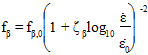 In the above equation, ζβ is the strain rate strengthening parameter for the β constituent as defined by user material constant 18. This value defaults to 0.0.