Perform a cylinder stability analysis on a composite tube.
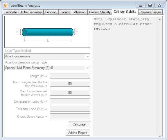
To begin the analysis, navigate to the Cylinder Stability tab in the Tube/Beam Analysis window as shown below. The basis of calculation for the various loadings is derived from NASA SP-8007 (Ref. 11.4). In addition, the interpretation of NASA SP-8007 found in The Behavior of Structures Composed of Composite Materials was referenced (Ref. 9.1, pp. 161-169).

- Load Type Applied - The analysis load type is selected from a drop-down menu. A pictorial depiction of the selected load type is displayed. The dimensions and loading required to define the analysis is depicted in the drawing.
Four basic load types are available (Axial Compression, Bending, External Pressure, and Torsion). There are also three combined load types available (Axial Compression + Bending, Axial Compression + External Pressure, and Axial Compression + Torsion).
The following limitations exist for the basic load types:- Axial Compression - Must be a balanced symmetric layup.
- Bending - Must be a balanced symmetric layup.
- Torsion - Must be a symmetric layup ([B]=[0]).
After creating a layup, it is recommended to examine the [A], [B], and [D] matrices to see if the limitations are satisfied prior to running the Cylinder Stability analysis. Check the [A], [B], and [D] matrices by executing the [ABD], [ABD] Inverse option under the "Laminate" module.
- Axial Compression Layup Type - If the laminate you define is used for an axial compression load scenario, select "Special, Mid Plane Symmetry [B] = 0" to specify that a symmetric laminate is used or "General, No Mid Plane Symmetry" to specify that an un-symmetric laminate is used. If an un-symmetric laminate is used, you have the option of specifying a Knock Down Factor in the bottom field (#8).
- Length - Specify the overall length of the cylinder.
- Max. Longitudinal Buckle Half Waves (m) - (Integer input) When buckling occurs in a cylinder in the longitudinal (axial) direction, it is accompanied by a number of perturbations or waves. The key to the analysis is to determine how many of these waves are present when a minimum buckling load is reached. For each integer value of "m", a unique buckling load is calculated. Helius Composite will begin with an (m=1) and will check for the minimum buckling load up to (m=Max. Longitudinal Buckle Half Waves). The default value is 50.
- Max. Circumferential Buckle Waves (n) - See instructions for (4), but this is specified for the circumferential direction.
- Compression Load - (Positive Number (+)) Specify the applied axial compression load on the cylinder.
- Torsional Load - (Positive Number (+)) Specify the applied torque on the cylinder.
- Knock Down Factor - If "General, No Mid Plane Symmetry" is chosen under (2) indicating that an unsymmetric laminate is being used in the analysis, you have the option of specifying a "Knock Down Factor" (also known as "correction factor") to correlate experimental data with theory.
- Calculate - Once the input has been completed, compute the cylinder stability analysis by clicking on the Calculate button. The output box on the right side of the window shows the results of the defined analysis. Each calculated result is preceded by the necessary assumptions for the results to be valid. Consider these whenever running a cylindrical buckling analysis. The following calculated results are displayed:
- Critical Compression Load - (units of force) The load at which the cylinder will buckle under an axial compression load.
- Critical Bending Load - (units of force) The moment per total end area of the cylinder at which the cylinder will fail, independent of other loads.
- Critical Bending Moment - (units of force x distance) The moment at which the cylinder will buckle, independent of other loads.
- Crit. Lateral Ext. Pressure - (units of force per area squared) The lateral external pressure at which the cylinder will buckle, independent of other loads.
- Crit. Hydrostatic Ext. Pressure - (units of force per area squared) The hydrostatic external pressure at which the cylinder will buckle, independent of other loads.
- Crit. Lateral Ext. Pressure for Long Cylinder - (units of force per area squared) The external pressure at which the cylinder will buckle, independent of other loads.
- Critical Torque - (units of force x distance) The torque at which the cylinder will buckle, independent of other loads.
- CTcr - This is a calculated factor which depends upon the stiffness and geometry of the cylinder. This factor must be greater than (>) or equal to (=) 500 for English units or 12.7 for SI units.
- n - The circumferential wave which gives the minimum critical buckling value.
- m - The axial half wave which gives the minimum critical buckling value.
- Simultaneous "m" & "n" - For the Axial Load + Bending Load Type, the buckling waves must match. This forces 'm" and "n" to be evaluated simultaneously or at the same values for both axial compression and bending.
- Rc - Unitless compression load ratio (applied load/calculated critical load)
- Rb - Unitless bending load ratio (applied load/calculated critical load)
- Rlp - Unitless lateral pressure load ratio (applied load/calculated critical load)
- Rhp - Unitless hydrostatic pressure load ratio (applied load/calculated critical load)
- Rt - Unitless torsion load ratio (applied load/calculated critical load)