Compute the transverse deflection of a sandwich beam for a wide variety of transverse loads and boundary conditions.
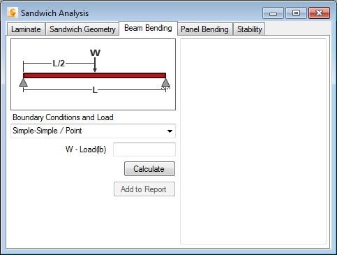
To perform a sandwich beam bending analysis, select the Beam Bending tab from the Sandwich Analysis window. Once the Laminate and Sandwich Geometry have been defined, complete the following five steps in the Beam Bending tab (see image below):

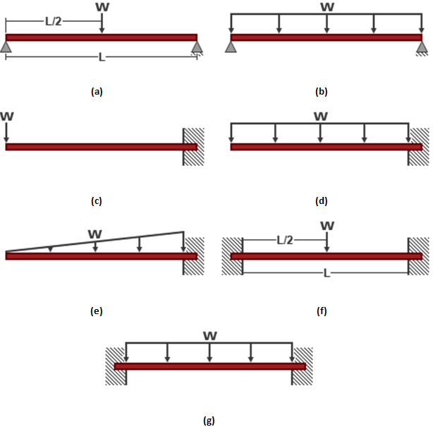
- Specify Boundary Conditions and Load Type - The Boundary Conditions and Load drop-down menu contains seven different combinations of beam end supports and transverse loading that can be selected:
- Simple-Simple / Point denotes simply supported conditions at both ends with a point load applied at mid-span (see part a of the image below).
- Simple-Simple / Uniform denotes simply supported conditions at both ends with a uniform distributed load (see part b of the image below).
- Free-Fixed / Point denotes a cantilevered beam with a point load applied at the free end (see part c of the image below).
- Free-Fixed / Uniform denotes a cantilevered beam with a uniform distributed load (see part d of the image below).
- Free-Fixed / Triangular denotes a cantilevered beam with a distributed load that varies linearly along the span (see part e of the image below).
- Fixed-Fixed / Point denotes clamped support conditions at both ends with a point load applied at mid-span (see part f of the image below).
- Fixed-Fixed / Uniform denotes clamped support conditions at both ends with a uniform distributed load (see part g of the image below).
- Specify Magnitude of Transverse Loading - If a point load is applied to the beam, the magnitude of the transverse load is specified in the box labeled W-Load in units of force. If a uniform distributed load is applied to the beam, the magnitude of the transverse load is specified in the box labeled w-Distributed Load in units of force/length. If a triangular distributed load is applied to the beam (as shown in part e of the image below), the magnitude of the transverse load is specified in the box labeled w-Distributed Load and the specified value is the force/length at the beam's mid-span.
- Calculate Results - After specifying all of the problem definition data, Click Calculate to compute the sandwich beam bending solution. The printed results consist of the following quantities:
- SIGfmax - The maximum in-plane stress in the laminated face sheet.
- TAUcmax - The maximum transverse shear stress in the core material. (This value can be compared to the allowable shear stresses for the selected core material).
- Deflection - The maximum transverse deflection caused only by bending deformation.
- Total Defl - The maximum transverse deflection, due to the combined effects of bending deformation and transverse shear deformation.
- SIGfdcr - Critical face dimpling stress. If the sandwich panel has a "honeycomb" core, the sandwich panel will fail by face dimpling type buckling if the computed maximum face sheet stress, SIGfmax, is greater than the critical face dimpling stress, SIGfdcr.
- SIGfwcr - Critical face wrinkling stress. If the computed maximum face sheet stress, SIGfmax, is greater than the critical face wrinkling stress, SIGfwcr, the sandwich beam will fail by face wrinkling type buckling.
