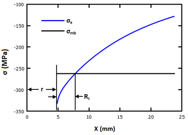
The point-stress method of determining the bolt strength (as laid out in the next section) assumes that laminate failure is initiated in tension and compression when the normal stress in the laminate reaches the ultimate strength some defined distance from the edge of the hole [43]. These distances are known as the characteristic lengths, Rt and Rc. These characteristic lengths depend on the laminate material properties and the relationship between the laminate width and hole diameter [44].
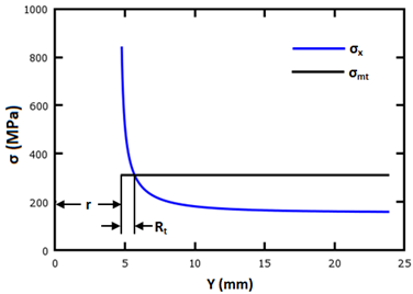
The characteristic length in tension, Rt, is calculated using the method proposed by Aluko [44]. First let's look at an open-hole coupon, analogous to the bolted joint subjected to an edge load. The tensile stress distribution σx is calculated along the plane (0,y) as shown below.
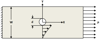
The tensile stress distribution is calculated using the complex stress functions proposed by Lekhnitskii and later implemented by Aluko for an orthotropic laminate with a circular opening [45,44]. The complex stress functions φ1 and φ2 are shown in Equations 10 and 11. The normal stress σx is defined in Eq. 12 [44,45].
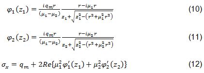
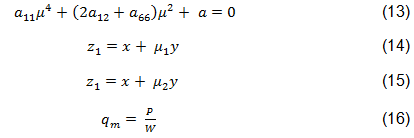
In Eqs. 10-12, r is the radius of the circular opening. µ1 and µ2 are the complex conjugate roots of the characteristic equation defining the orthotropic nature of the laminate, shown in Eq. 13 [44]. The complex variables z1 and z2 are defined by Aluko in Eqs. 14 and 15. qm is the applied stress at infinity, given by Eq. 16 [44].
The location of intersection between the mean tensile stress σmt, shown in Eq. 17, and the tensile stress distribution σx, defines the location of Rt as shown below [44].
The characteristic length in compression, Rc, is calculated using Aluko's approach [44]. In this method a bearing test coupon is evaluated analytically in a manner similar to that used for the tensile case. The bearing stress distribution σx is calculated along the plane (x,0) as shown below.
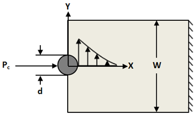
This is accomplished using the complex stress functions from Lekhnitskii and Aluko for an orthotropic plate with a circular intrusion [45,44]. These expressions are shown in Equations 18-20 [44].

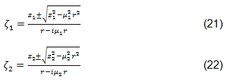
The quantities u1, u2, v1, v2, q1, q2, p1, p2, and D are constants which depend on material properties and the boundary conditions at the interface between the bolt and plate [44,46]. The quantities A and B depend on the loading, joint geometry, and the roots of the characteristic equation µ1 and µ2 [44,45]. ζ1 and ζ2 are the complex functions that map the stress field from the complex plane to the Cartesian coordinate system. These functions are given in Equations 20 and 21, where the sign is chosen such that the magnitudes of ζ1 and ζ2 are both greater than or equal to one [44].
The location of Rc is computed as the intersection of the bearing stress distribution σx and the mean bearing stress σmb (defined in Eq. 23) imparted on the coupon by the inclusion under the influence of the arbitrary point load Pc.

The application of this method is shown graphically below.
