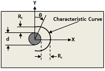
Now that the characteristic lengths have been determined, the characteristic curve is constructed using Eq. 24. This characteristic curve, as proposed by Chang, is shown below [46]. As shown, d is the diameter of the hole, θ varies from 0 to π, and rc(θ) defines the characteristic curve. This curve defines the location in the plate where the in-plane laminate stresses are evaluated and the failure criterion is applied [44].


Superposition is used to estimate the entire 2-D stress field around the bolt due to combined effects of the concentrated bearing load Pc and the distributed bypass load P, applied at infinity. These combined results are evaluated along Chang's characteristic curve [46].
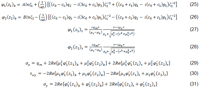
The complex stress functions used in this superposition method are based on those by Lekhnitskii and Aluko and are shown in Eqs. 25-31 [45,44]. Subscripts b and t denote the filled-hole and open-hole solutions, respectively.

In Eqs. 25 and 26, c0 and c1 are determined by material constants, loading, and contact boundary conditions [44].
With the stress field estimated along the characteristic curve, the finite width correction factor, FWC, is calculated using Eqs. 32 and 33 [47,44]. KT and KT∞ represent the stress concentration factors for a finite width plate and an infinite width plate. A11, A12, and A66 are components of the in-plane laminate stiffness matrix, r is the radius of the hole in the plate, and W is the width of the plate [44,47].
The FWC factor, is applied as shown in Eq. 34, where σN and σN∞ are the notched strengths for a finite and infinite width laminate plate [44].
