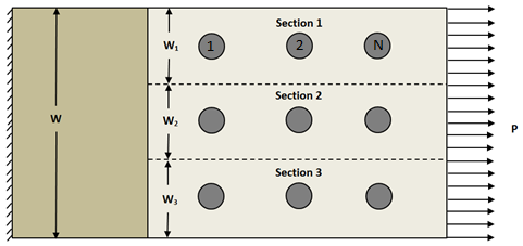
Load sharing calculations are performed to determine the critical bolt in the joint. In these calculations, we assume the distributed edge load is shared equally among all the rows of bolts in the joint as shown below. We assume Sections 1-3 do not interact with one another. Thus, each section can be evaluated individually. A single section is used to determine the relative load fraction for the bolts numbered 1-N in the loading direction.

Each row of bolts in the joint (if more than one exists) is considered independently. The load sharing within the row is estimated using the equivalent thickness model used by Heslehurst [42]. The relative load fractions are determined using the effective bolt bending stiffness Kf given by Eq. 1 and the plate stiffness Kp given by Eq. 2 [42].

A, B, and H are empirically determined constants. tav is the average thickness of the plates in the joint, d is the diameter of the bolt, and Ap is the cross-sectional area of the plate considered. Ep is the Elastic modulus of the plate in the direction of loading and l is the spacing between bolts in the loading direction [42].
The bolted connection tool supports up to 5 bolts in a row. The load distribution for a single bolt is simply P. Two bolts in a single row equally share the load P. For a row with three bolts, the relative load fractions are given by Eqs. 3 and 4 [42].

For a row with four bolts, the relative load fractions are determined by Eqs. 5 and 6 [42].

For a row with five bolts, the relative load fractions are determined by Eqs. 7-9 [42].

Each row is analyzed and the bolt having the largest relative load fraction is identified as the critical bolt in the analysis. This bolt, along with its reaction load and surrounding geometry, is passed to the solver to determine the stress field around the bolt.