Compute the critical buckling load of a laminated sandwich plate subjected to uniaxial in-plane compression.
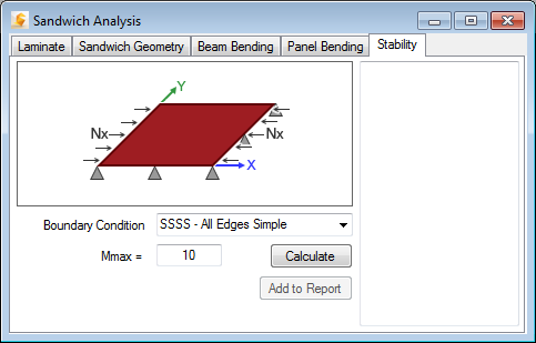
To perform a sandwich panel stability analysis, select the Stability tab from the Sandwich Analysis window. Once the Laminate and Sandwich Geometry have been defined, complete the following steps in the Stability tab (see image below).

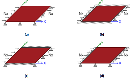
- Specify Boundary Conditions - The Boundary Condition drop-down menu contains four different sets of beam end supports that can be selected.
- SSSS denotes simply supported conditions on all four edges of the panel (see part a of the image below).
- CCCC denotes clamped conditions on all four edges of the panel (see part b of the image below).
- SSCC denotes simply supported conditions on the loaded edges and clamped conditions on the non-loaded edges (see part c of the image below).
- CCSS denotes clamped conditions on the loaded edges and simply supported conditions on the un-loaded edges (see part d of the image below).
- Specify Number of Buckling Modes to Examine - The m max box is used to specify the number of axial buckling modes to examine in the search for the minimum buckling load. For example, if mmax is specified as 10, the analysis would consider buckled mode shapes that included between 1 and 10 axial buckling waves. From this group of 10 different buckling modes, Helius Composite would identify the buckling mode with the lowest buckling load. For panels that are approximately square, mmax = 10 is usually sufficient to ensure that the critical buckling mode is identified correctly. For panels that are much longer than wide, it is often necessary to increase mmax into the range of 10 < mmax < 100.
- Calculate Results - Click on the Calculate button to compute the solution. The results are shown in the display window. The printed results consist of the following quantities:
- Panel Data - Length L, Width W, Weight, Core Type, Core thickness, and Face Sheet thickness.
- Critical m - Corresponds to the number of buckling waves in the axial direction that yields the lowest buckling load.
- Transverse Shear Flexibility - The transverse shear flexibility of the core is compared against the Critical Transverse Shear Flexibility to determine the buckling mode.
- Critical Transverse Shear Flexibility - Critical transverse shear flexibility of the core. If the actual transverse shear flexibility of the core meets or exceeds the critical value, the buckling mode will be Core Shear, otherwise it is Overall.
- Overall Instability Critical - Stress at which the sandwich panel will fail in an overall, complete panel, buckling mode. This failure stress will not be displayed if the Transverse Shear Flexibility meets or exceeds the Critical Transverse Shear Flexibility.
- Core Shear Instability Critical - This failure can occur due to a panel having face sheets which are too stiff. Essentially, the core material will fail in transverse shear. This failure stress will not be displayed if the Transverse Shear Flexibility does not meet or exceed the Critical Transverse Shear Flexibility.
- Critical Face Sheet Wrinkling Stress - Buckling stress required to cause wrinkling of the face sheets i.e., face wrinkling type buckling. This form of buckling is only applicable for sandwich panels with a honeycomb core.
- Critical Face Sheet Dimpling Stress - Buckling stress required to cause dimpling of the face sheets, i.e., face dimpling type buckling. This form of buckling is only applicable for sandwich panels with a honeycomb core.
