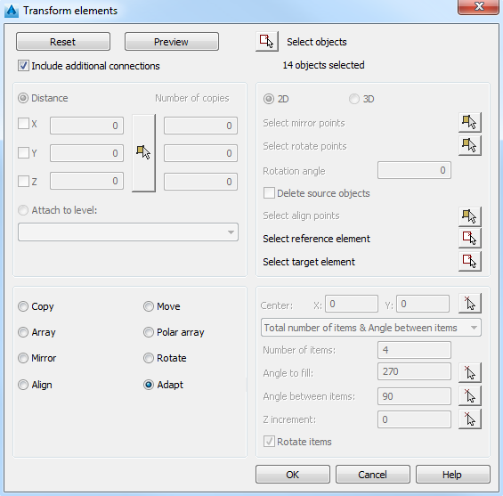
1. Reset
2. Preview
Closes the Transform elements dialog box and displays the result in the current drawing area.
3. Include additional connections
The beam will be copied with its connections, in case that the same situation applies for the target as at the origin.
This behavior is controlled by a default named Automatically detect corresponding objects at destination.
4. Select objects
Temporarily closes the Transform elements dialog box and allows selecting objects using normal AutoCAD techniques. After confirming the selection the Transform elements dialog box appears.
5. Copy
This option allows creating several copies of the selected objects. The parameters are set in the top-left panel of the Transform elements dialog box.
X, Y, Z
Define the relative X, Y, Z displacement.
 Clicking this button temporarily closes the dialog box so that you can specify two points defining the distance and the direction in which the copied objects are to be created.
Number of copies
It defines the number of copies that are to be created by the command. Only the first field is active.
6. Move
This option allows moving an object from one location to another. The parameters are set in the top-level panel of the Transform elements dialog box.
X, Y, Z
Define the relative X, Y, Z displacement:
- in a defined point
- specified distance in a specified direction
7. Array
This option allows creating copies in a rectangular array, in 2D or 3D. You can control the number of rows along each direction of the UCS and the distance between them.
The parameters are set in the top-level panel of the Transform elements dialog box.
X, Y, Z
Defines the distance between elements in each direction of the UCS.
Clicking this button temporarily closes the dialog box so that you can specify two diagonal corners of a rectangle to define the distance between the rows in X and Y direction.
Number of copies
It defines the number of rows in each direction of the UCS.
8. Polar array
This option allows placing copies of an object about a specified center point or about a rotation axis. The parameters are set in the bottom-right panel of the Transform elements dialog box.
Center
Defines the center point of the polar array by coordinates or by on-screen selection. Clicking the
 button temporarily closes the dialog box so that you can specify the center point in the drawing area.
Method selection
Sets the method used to place the new objects. This setting controls which of the fields are available for specifying values.
The three variables of polar array are the number of copies, the angle to be filled and the angle between items. It is necessary to know at least two of these variables.
- Total number of items & Angle between items: Creates n copies at equal angles between them. The angle to be filled is calculated automatically.
- Total number of items & Angle to fill: Fits a given number of objects within the specified angle. The angle between two consecutive items is calculated automatically.
- Angle to fill & Angle between items: Creates as many copies as possible, within a given angle, at defined intervals.
Number of items
Defines the number of elements in the polar array.
Angle to fill
Defines the size of the included angle between the base points of the first and the last elements in the polar array and the center of the array, and the direction:
- A positive angle generates a counterclockwise array rotation.
- A negative angle generates a clockwise array rotation.
Angle between items
Defines the size of the included angle between the base points of two consecutive array objects and the center of the array.
and use the mouse to define the Angle to fill and the Angle between items.
Z increment
Defines the distance on the rotation axis in Z direction.
Rotate items
Rotates each array element.
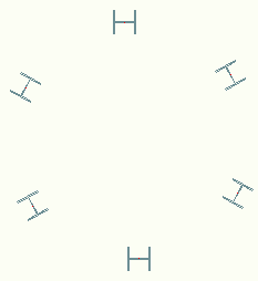
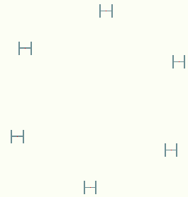
Example:
|
Polar array - rotated elements |
Polar array not rotated elements |
|
|
9. Mirror
This option allows creating a symmetrical copy of the selected objects about a specified axis (mirror line) or plane. The mirror line is defined by two points. You can choose whether to erase or retain the original objects. The parameters are set in the top-right panel of the Transform elements dialog box.
2D
Creates a copy about a mirror line in 2D.
3D
Creates a copy about a mirror line in 3D.
Select mirror points
Clicking
 temporarily closes the dialog box so that you can specify two points of the mirror line.
For mirroring in 3D, three points are necessary to define the mirroring plane.
Delete source objects
If selected, the mirrored object is placed on the drawing and the original object is deleted.
10. Rotate
This option allows to copy and rotate in 2D (according to the UCS) or in 3D by specifying 2 points that define the rotation axis. The parameters are set in the top-right panel of the Transform elements dialog box.
2D
Rotates the object about a defined center point.
3D
Rotates the object about a rotation axis.
Select rotate points
For a rotation in plan, click
to select the rotation center. The dialog box closes temporarily so that you can select the point or enter the coordinates.
For a rotation in 3D, click
and select two points to define the rotation axis. The dialog box closes temporarily so that you can click the points on the drawing or define them by entering the coordinates.
Rotation angle
Defines the rotation angle and direction. Enter an angle value between 0 and 360 degrees.
11. Align
This option allows to create a copy of the selected object aligned with another object by specifying three pairs of points: three points define the source object reference plan and three points define the destination plane.
Example
Click
to select
The base point of the source object will be moved to the base point of the destination and the X and Y axes of the source object will be aligned within the destination plane.
1 2 3 4 5 6
1: the base point of the source object
2: the base point of the destination
3: defines the X axis direction of the source object
4: defines the X axis direction of the destination
5: defines the Y axis direction of the source object
6: defines the Y axis direction of the destination
1, 3, 5 - define the source reference plan
2, 4, 6 - define the destination plan
12. Adapt
Copies a selected object in a same position relative to another object
Select reference object
Select target object