Learn the steps of creating a straight beam using the Dynamo extension for Advance Steel.
- On the Dynamo start page, click New to create a new blank file.
- In the tree menu on the left, expand the AdvanceSteel tab
 Beams StraightBeam and select ByStartPointEndPoint. This command will create an Advance Steel beam in Dynamo, using a start point and an end point.
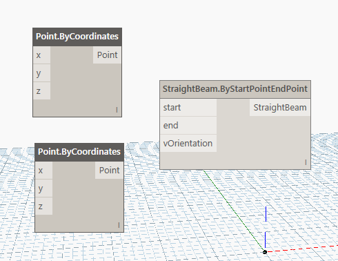
- Notice that the StraightBeam.ByStartPointEndPoint node appears in the Dynamo workspace:
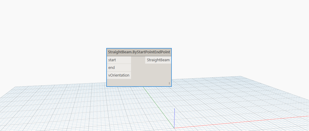
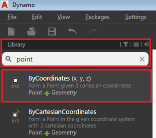
- In order to output a straight beam, you need to provide a start point, an end point and a vector orientation used to determine the strong axis of the beam. To select the two required points, you can search the word "point" in the library, using the Library Search box on the left tree menu.
- From the search results list, select ByCoordinates (x, y, z) to create a point using the three x, y, z coordinates:
 The Point.ByCoordinates node appears in the workspace. This node requires three coordinates to generate a point. Therefore, the input is 3 numbers and the output is one point (with 3 coordinates):
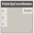 Note: If a node can accept inputs, they are shown on the left side. The output of the node is always on the right side.
 - Repeat the previous step to create a second Point.ByCoordinates node.
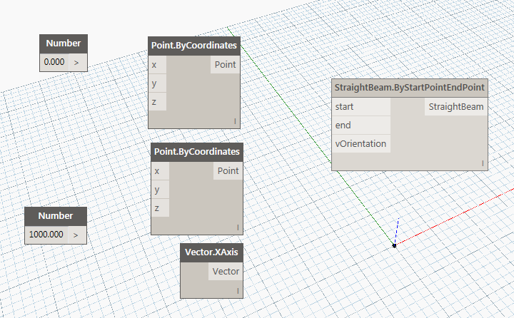
- Click and drag the nodes to arrange them like in the following image:
- Search for the word "number" in the Library search box and select Number from the search results list. The Number node appears in the workspace.
- Repeat the previous step, to create another Number node.
- Change the value in the new Number node to 1000, by double-clicking on the value (0.000) and typing 1000. Press Enter or click outside the node to save the changes.
- Search for "xaxis" in the Library search box and select XAxis from the search results list. The Vector.XAxis node appears in the workspace.
- Rearrange the nodes by dragging them in the workspace, similarly to the image below:
Connect the Nodes
Now that you have all the required nodes, you need to connect them in order to make them work together.
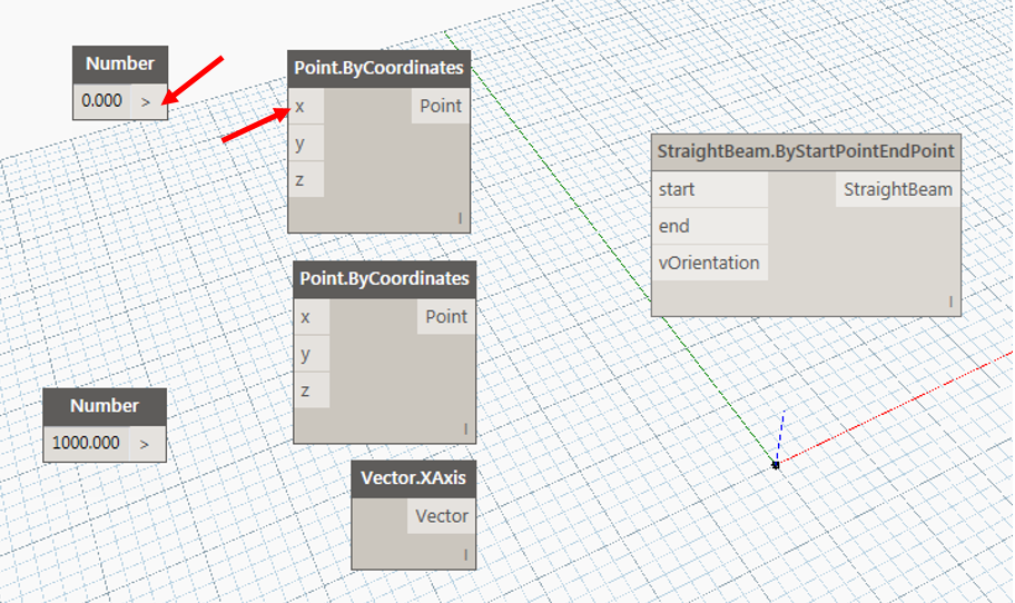
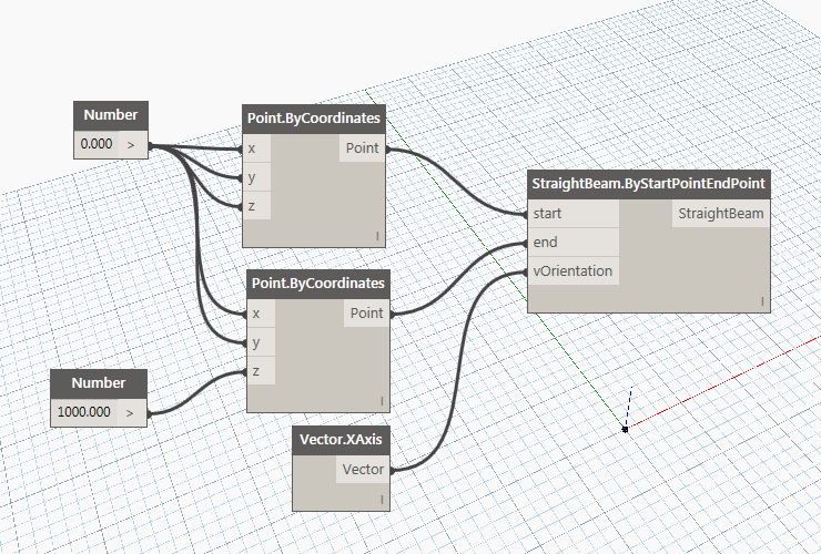
Scheme significance
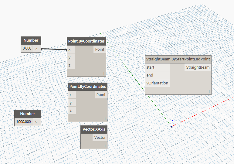
On the left side, there are two numbers, in the middle there are two points and a vector and on the right there is the beam. The two numbers are used for the coordinates of the points. The first number (0) is used as the X,Y coordinates for both points but also for the Z coordinate of the first point. The second number (1000) is used for the Z coordinate of the second point.
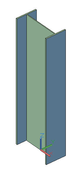
Notice that a single number can output to many nodes at the same time (5 in this example). The vector orientation is required to define the direction of the beam's strong axis. Therefore, this creates a beam with the length of 1000mm, from the (0,0,0) origin to the (0,0,1000) point, with the strong axis facing the X direction.
In the bottom left corner of the Dynamo window, you will notice that the Automatic option is selected; this means that the Advance Steel model is being updated in real time, according to the changes made in Dynamo. Consequently, if you turn to Advance Steel, you will see that the beam you designed in Dynamo will appear in Advance Steel: