To access the command
Quick views tool palette:

Command line: _AstM11CommCreateModelView
To define a model view by selecting one point in the UCS
- Place the UCS in a suitable position. The model view will display the XY plane.
- Quick views tool palette: Click
.
- In the dialog box, select
 .
.
- Select a point that you wish to be the center of the model view area.
- On the command line, enter the view name and press <Enter>.
- A default view box appears and the arrows for defining the default view direction.
- Select one of the displayed arrows to define the view direction and press <Enter>.
- The model view is created and appears in the Project Explorer.
Example:
You can create a model view to display the intersection of elements. It is useful to create easier the necessary joints. The default view direction is top view.

To define a model view by two points
- Select a suitable UCS.
- Quick views tool palette: Click
.
- In the dialog box, select
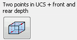 .
.
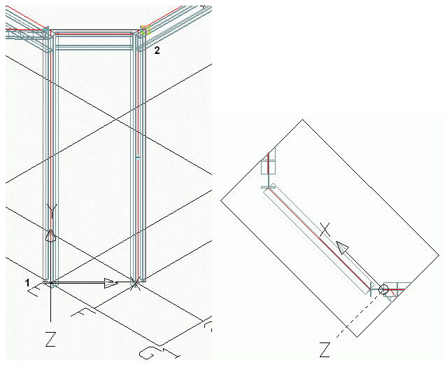
- Select two diagonal points in the view plane.
- On the command line, enter the front depth and press <Enter>.
- On the command line, enter the rear depth and press <Enter>.
- Enter the view name and press <Enter>.
- A default view box appears with arrows to define the view direction.
- Select one of the displayed arrows to define the view direction and press <Enter>.
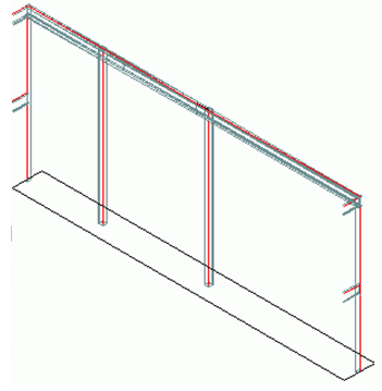
- The model view is created and appears in the Project Explorer.
Example:
To define a model view at grid line
- Quick views tool palette: Click
.
- In the dialog box, select
 .
.
- Select a grid line and press <Enter>.
- Enter the view name and press <Enter>.
- Select one of the displayed arrows to define the view direction and press <Enter>.
- The model view is created.
Example:
To define a model view at a joint box
- Quick views tool palette: Click
.
- In the dialog box, select
 .
.
- Select the joint box and press <Enter>.
- On the command line, enter the view name and press <Enter>.
- Select one of the displayed arrows to define the view direction and press <Enter>.
- The model view is created.
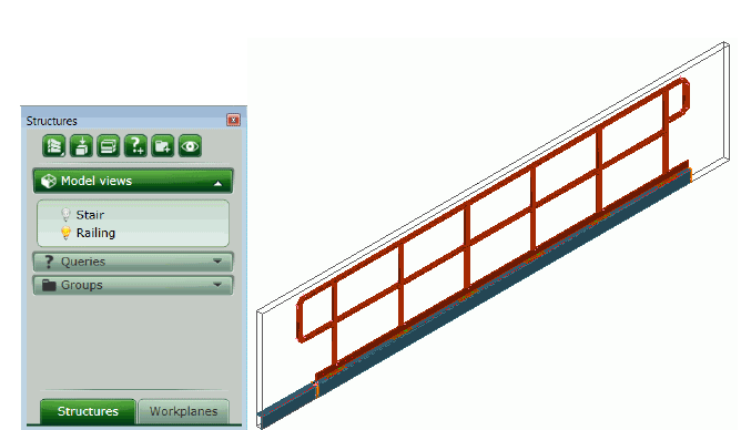
Example: Model view for a railing