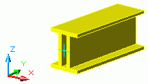
Several profiles welded to each other are created at a system line. The sections are handled as a single section so that a trim will affect all sections.
Create welded beams
You can create welded sections like simple sections, by entering a start point and an end point according to the current coordinate system. The current user coordinate system (UCS) determines the position of the sections main axes: the beam web runs in the Z direction of the UCS - or in other words, the top of the section is in the Z direction.

To create welded beams, use the Welded beams flyout on the Beams panel of the Objects tab.
Additionally, you can create custom welded sections and store them in a library. Using the properties dialog box, you can control the section class and the section of each individual element in the welded beam.
Welded beams behavior
During the numbering process, in drawings and lists, the welded beams behave in two ways:
- As one profile, with a compound section
- As separate profiles