Ensure the precision required for your models.
There are several precision features available, including
- Polar tracking. Snap to the closest preset angle and specify a distance along that angle.
- Locking angles. Lock to a single, specified angle and specify a distance along that angle.
- Object snaps. Snap to precise locations on existing objects, such as an endpoint of a polyline, the midpoint of a line, or the center point of a circle.
- Grid snaps. Snap to increments in a rectangular grid.
- Coordinate entry. Specify a location by its Cartesian or polar coordinates, either absolute or relative.
The three most commonly used features are polar tracking, locking angles, and object snaps.
Polar Tracking
When you need to specify a point, such as when you create a line, you can use polar tracking to guide the movement of your cursor in certain directions.
For example, after you specify the first point of the line below, move your cursor to the right, and then enter a distance in the Command window to specify a precise horizontal length for the line.

By default, polar tracking is turned on and guides your cursor in a horizontal or vertical direction (0 or 90 degrees).
Locking Angles
If you need to draw a line at a specified angle, you can lock the angle for the next point. For example, if the second point of a line needs to be created at a 45 degree angle, you would enter <45 in the Command window.

After you move your cursor in the desired direction along the 45-degree angle, you can enter the length of the line.
Object Snaps
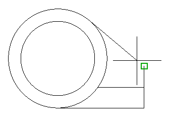
By far, the most important way for you to specify precise locations on objects is to use object snaps. In the following illustration, several different kinds of object snaps are represented by markers.

Object snaps become available during a command whenever AutoCAD prompts you to specify a point. For example, if you start a new line and move your cursor near the endpoint of an existing line, the cursor will automatically snap to it.
Set Default Object Snaps
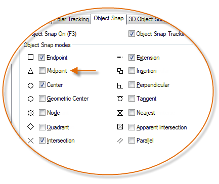
Enter the OSNAP command to set the default object snaps, which are also called "running" object snaps. For example, you might find it useful to turn on the Midpoint object snap by default.
Recommendations
- At any prompt for a point, you can specify a single object snap that overrides all other object snap settings. You hold down Shift, right-click in the drawing area, and choose an object snap from the Object Snap menu. Then move the cursor to select a location on an object.
- Make sure that you zoom in close enough to avoid mistakes. In a densely populated model, snapping to the wrong object will result in an error that can propagate throughout your model.
Object Snap Tracking
During a command, you can align points both horizontally and vertically from object snap locations. In the following illustration, you first hover over endpoint 1 and then hover over endpoint 2. When you move your cursor near location 3, the cursor locks into the horizontal and vertical location shown.
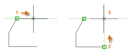
You can now finish creating the line, circle, or other object that you were creating from that location.
Verify Your Work
Recheck your geometry to catch mistakes early. Enter the DIST command (or just DI) to measure the distance between any two points in your model.
For example, you might need to find the clearance between two points shown, which might represent the corner of a wall and a small table, or perhaps a 2D section of a plastic part and a wire.
After you enter DIST, click the endpoint on the corner (1). Next, hold down Shift as you right-click, and then choose Perpendicular from the object snap menu. Finally, click the circle (2).
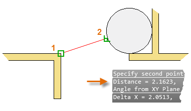
The number of decimal places and unit style displayed in the result is controlled by the UNITS command.
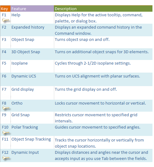
Handy Function Key Reference
The keyboard function keys all have assignments in AutoCAD. The ones that are most commonly turned on and off are indicated with a key.
